
Convert a platinum RTD reading or test temperature using the selected Pt sensor type, curve, and explicit ohms, kOhm, deg F, or deg C units.
Advanced options
Calculation details
Table of contents
How to use our RTD Callendar-Van Dusen Resistance and Temperature Calculator
- Choose whether you have a resistance reading or a known temperature.
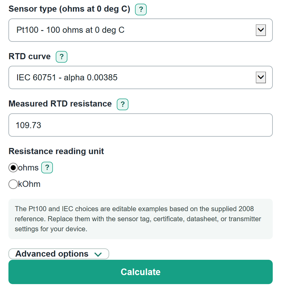
- Select the exact Sensor type and RTD curve from the probe tag, datasheet, calibration certificate, or transmitter setup.
- Enter the visible instrument value and choose its matching unit under Resistance reading unit or Known temperature unit.
- Click Calculate, then check the normalized input card to confirm the calculator used the intended ohms or deg C value.
- Compare the main result with your procedure or reference instrument, remembering that wiring resistance and sensor tolerance can cause a real measurement to differ.
Definitions
RTD: Resistance temperature detector, a sensor whose electrical resistance changes with temperature.
Pt100, Pt500, Pt1000: Platinum RTDs rated at 100, 500, or 1000 ohms at 0 deg C.
R0: The selected resistance at 0 deg C. It is 100 ohms for a Pt100, 500 ohms for a Pt500, and 1000 ohms for a Pt1000.
RTD curve: The coefficient set used to match resistance and temperature. The IEC 0.00385 and US industrial 0.00392 curves are different.
Callendar-Van Dusen equation: The platinum RTD equation that uses coefficients A, B, and, below 0 deg C, C to calculate resistance from temperature or temperature from resistance. [1]
Normalized input: Your entered value after conversion to the equation units: ohms for resistance and deg C for temperature.
Common mistakes and quick fixes
Mistake: Entering 1.097 as though it were ohms when the meter shows 1.097 kOhm.
Fix: Enter the reading in Measured RTD resistance and choose kOhm under Resistance reading unit.
Mistake: Using Pt100 when the probe tag says Pt1000.
Fix: Set Sensor type to the marking on the probe, transmitter, or calibration certificate.
Mistake: Treating a deg F setpoint as deg C.
Fix: Enter the number in Known temperature and select the printed unit under Known temperature unit.
Mistake: Guessing the curve because both choices look close.
Fix: Match RTD curve to the sensor datasheet or transmitter configuration; IEC 60751 and US industrial curves use different coefficients.
Mistake: Comparing loop resistance that includes wiring with Expected RTD resistance (ohms).
Fix: Correct the field reading for lead-wire resistance before entering Measured RTD resistance, or use a measurement method that removes the wiring effect.
Limitations & Key Assumptions / Boundary Conditions
- The calculation applies only to platinum RTDs using the selected IEC 0.00385 or US industrial 0.00392 coefficient curve.
- It accepts temperatures from -200 to 850 deg C and rejects resistance outside the matching selected-curve endpoints.
- Enter sensor resistance after any needed external lead-wire correction. A 2-wire loop reading can include wire resistance and produce a shifted temperature.
- Sensor tolerance class, aging, self-heating, installation effects, and a transmitter's own calibration adjustment are not applied as corrections.
- Use the sensor tag, calibration certificate, datasheet, or transmitter setup to choose Sensor type and RTD curve; a wrong selection can give a plausible but incorrect result.
- Number detail and number style change only how the answer is displayed, not the underlying calculation.
Methodology
Calculation method
The calculator first converts the entered resistance to ohms or the entered temperature to deg C. It then selects R0 from Sensor type and the A, B, and C coefficients from RTD curve. R is resistance in ohms, R0 is resistance at 0 deg C, and T is temperature in deg C.
R = R0 * (1 + A * T + B * T^2)
This equation is used when T is 0 deg C or higher.
R = R0 * (1 + A * T + B * T^2 + C * (T - 100) * T^3)
This separate branch is used below 0 deg C. The selected coefficient sets and the two temperature branches follow the Callendar-Van Dusen platinum RTD method. [1]
Finding temperature from resistance
For a nonnegative result, the calculator solves the quadratic branch directly when valid. For a sub-zero result, it searches the selected curve between -200 and 850 deg C until the remaining temperature interval is less than 0.0000001 deg C.
T deg C = (T deg F - 32) * 5 / 9
For the reverse temperature conversion, the calculator uses T deg F = T deg C * 9 / 5 + 32.
Worked example
With a Pt100, the IEC 60751 curve, and a known temperature of 212 deg F, the normalized temperature is 100 deg C. Applying the nonnegative equation gives an expected resistance of 138.5055 ohms, or 0.1385055 kOhm.
Calculation scope
The equation models the selected sensor curve, not the complete measurement system. The entered resistance is treated as the RTD element resistance after any external lead-wire correction, and tolerance class is not added as a curve adjustment.