
Calculate double-acting hydraulic cylinder push and pull force, motion, oil volume, and an ideal rod buckling comparison from common US measurements.
Advanced options
Calculation details
Table of contents
How to use our Hydraulic Cylinder Force, Speed, Flow and Rod Buckling Calculator
- Choose Available flow if you know flow reaching the cylinder, or Desired speeds if you need to size the required flow.
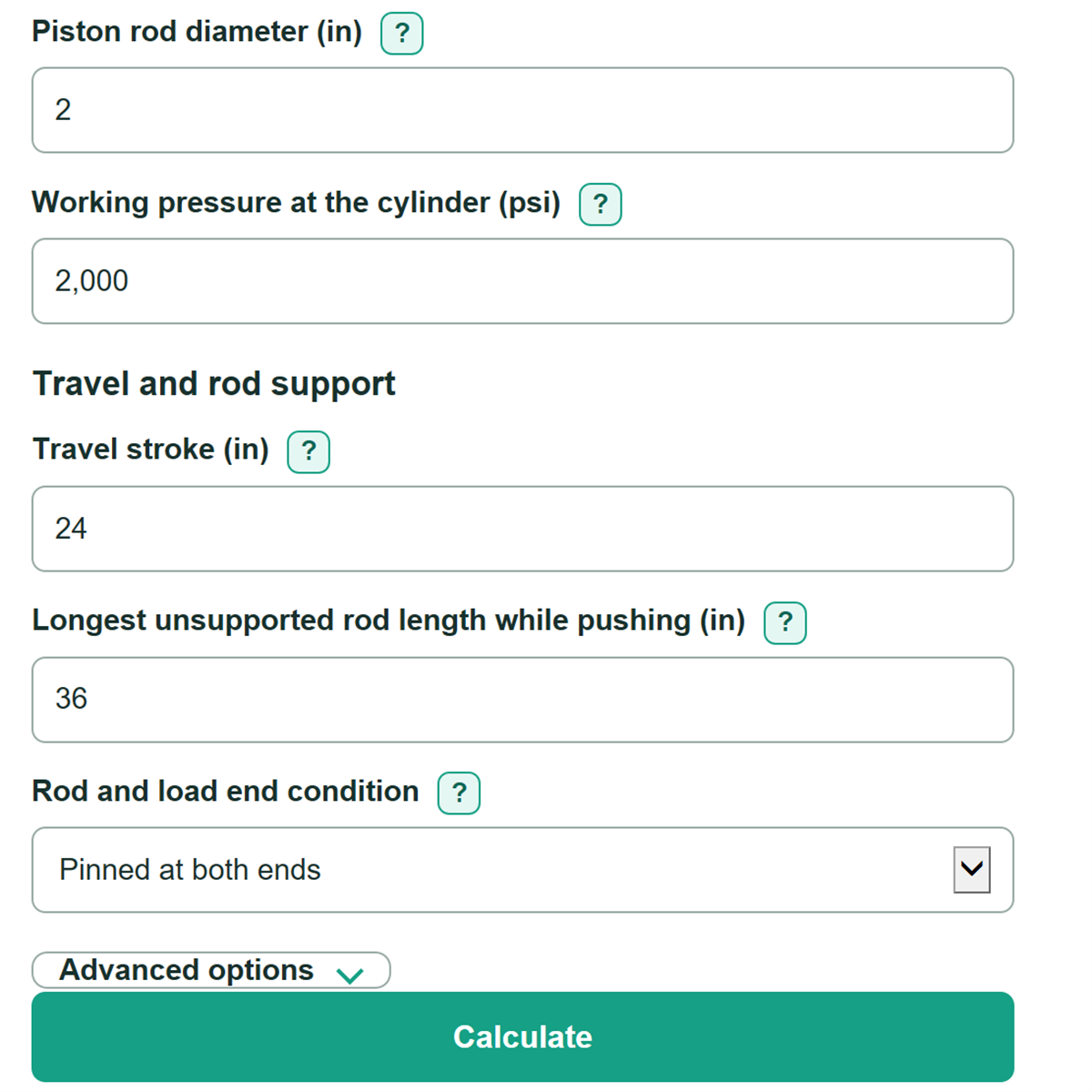
- Enter the Cylinder bore diameter, Piston rod diameter, and Working pressure at the cylinder from the cylinder data or measured operating conditions.
- Enter Travel stroke for motion time and oil volume. Enter Longest unsupported rod length while pushing from the fully extended machine geometry; it may differ from travel stroke.
- Choose the Rod and load end condition, then enter available flow or both desired speeds for the selected motion input.
- Check that usable extend force meets the load need and that the ideal buckling capacity divided by extend force is above 1. Then compare the ideal buckling result with the cylinder manufacturer's column-load limit before using it for a design decision.
Definitions
Full piston area: The circular area inside the cylinder bore. Pressure on this area creates extend force.
Rod-side annular area: The piston area minus the rod cross-section area. This smaller area creates retract force.
Back pressure: Pressure on the opposite side of the piston that resists motion and reduces usable force.
Mechanical efficiency: The percent of ideal hydraulic force kept after estimated mechanical losses. A value of 100 percent is ideal.
Effective-length factor: A number based on the selected rod and load end condition. It changes the unsupported length used in the Euler buckling calculation.
Ideal Euler rod buckling capacity: A straight-column estimate of the compressive load where an ideal rod can buckle.
Ideal buckling capacity divided by extend force: Ideal buckling capacity divided by usable extend force. A value above 1 means the ideal capacity is greater than calculated push force; it is not a design safety factor.
US gallon: This calculator uses 231 cubic inches per US gallon for flow and oil-volume conversions. [1]
Common mistakes and quick fixes
Mistake: Using the pump relief setting for Working pressure at the cylinder.
Fix: Use the pressure measured or specified at the cylinder port during the actual move.
Mistake: Entering Travel stroke again as Longest unsupported rod length while pushing without checking the extended assembly.
Fix: Measure the longest unbraced rod segment from the gland-side support to the guided load point.
Mistake: Expecting Usable retract force to equal Usable extend force.
Fix: Keep the actual Piston rod diameter ; the rod reduces retract-side working area.
Mistake: Entering pump nameplate flow as Available flow to the cylinder while other functions operate.
Fix: Enter flow that actually reaches this cylinder after valve restrictions and shared circuit demand.
Mistake: Treating Ideal Euler rod buckling capacity as an approved working load.
Fix: Use it only as a preliminary comparison and apply the manufacturer cylinder column-load limit and machine safety review.
Mistake: Ignoring Rod-end back pressure during extension or Cap-end back pressure during retraction when measurements are available.
Fix: Check Motion input and then recalculate. Enter the opposing port pressure for each direction to reduce the force estimate appropriately.
Limitations & Key Assumptions / Boundary Conditions
- Force estimates use entered pressure, geometry, back pressure, and mechanical efficiency. Actual force can differ because of seal friction, leakage, pressure drop, changing pump flow, and load dynamics.
- Speed and time are geometric estimates. They exclude acceleration, valve response, cushioning, hose expansion, fluid compression, dwell time, and flow changes caused by other hydraulic functions.
- The rod buckling result is an ideal Euler screening estimate for a solid, straight circular rod under centered axial compression. Side load, misalignment, shock, threads, stops, gland strength, mounting details, and cylinder construction can control first.
- The selected rod and load end condition is an ideal restraint model. If the actual load guidance or mounting restraint is uncertain, use the cylinder manufacturer's column-load guidance instead.
- Travel stroke and longest unsupported rod length are separate inputs. Do not assume they are equal unless the extended machine geometry confirms it.
- A ratio above 1 only means ideal Euler capacity exceeds the calculated extend force. It does not establish a safe working load or replace a machine safety review.
Methodology
Force and motion calculation
The calculator finds the full piston area A_p (full piston area) and rod area A_r (rod cross-section area). The rod-side annular area A_a (retract working area) is the difference between them.
A_p = π x bore^2 / 4
A_r = π x rod^2 / 4
A_a = A_p - A_r
Extend force uses working pressure on the full piston area, less rod-end back pressure on the annular area. Retract force uses working pressure on the annular area, less cap-end back pressure on the full piston area. Both are multiplied by mechanical efficiency η (efficiency as a decimal).
F_extend = (P_work x A_p - P_rod_back x A_a) x η
F_retract = (P_work x A_a - P_cap_back x A_p) x η
In Available flow mode, the calculator changes US gpm to cubic inches per second using 231 cubic inches per US gallon and 60 seconds per minute. [1]
Q_in3_s = Q_gpm x 231 / 60
extend speed = Q_in3_s / A_p
retract speed = Q_in3_s / A_a
In Desired speeds mode, it reverses the same relationship to find cap-end and rod-end flow. Full-stroke time is travel stroke divided by the speed for that direction. Oil volume is working area times travel stroke divided by 231.
required flow (US gpm) = speed x area x 60 / 231
travel time = travel stroke / speed
Ideal rod buckling comparison
The buckling check uses Euler's ideal elastic-column equation. E is rod elastic modulus in psi, I is the circular rod area moment, K is the effective-length factor from the selected end condition, and L is the longest unsupported rod length while pushing.
I = π x rod^4 / 64
P_cr = π^2 x E x I / (K x L)^2
The displayed ratio divides ideal Euler capacity P_cr by usable extend force. The calculator stops if usable extend force is zero or negative because that ratio would not be meaningful.
buckling load ratio = P_cr / F_extend
Worked example
With a 4 in bore, 2 in rod, 2,000 psi working pressure, 10 US gpm, 24 in travel stroke, 36 in unsupported rod length, pinned ends, 100 percent efficiency, and zero back pressure, usable extend force is about 25,133 lbf. Estimated extend speed is about 3.064 in/s, retract speed is about 4.085 in/s, and ideal Euler capacity is about 173,453 lbf. The ideal buckling capacity divided by extend force is about 6.90.
Calculation choices
Blank optional back-pressure fields are treated as 0 psi. The default rod elastic modulus of 29 million psi is an editable steel example. The calculator keeps travel stroke separate from unsupported rod length because stroke controls volume and time while unsupported length controls the buckling calculation.