
Estimate cyclone D50 cut size, particle collection, pressure drop, inlet velocity, and fan power using airflow and clear inlet dimensions.
Cyclone inlet
Particle check
Pressure allowance
Advanced options
Gas properties
Performance assumptions
Calculation details
Table of contents
How to use our Cyclone Separator Cut Size Calculator
- Choose Airflow basis from the label on your fan schedule or test record. Select Actual airflow for ACFM, or Standard airflow for SCFM.
- Enter Airflow (ACFM or SCFM, as selected), then enter Operating pressure (psig) and Operating temperature (F) only when Standard airflow is selected.
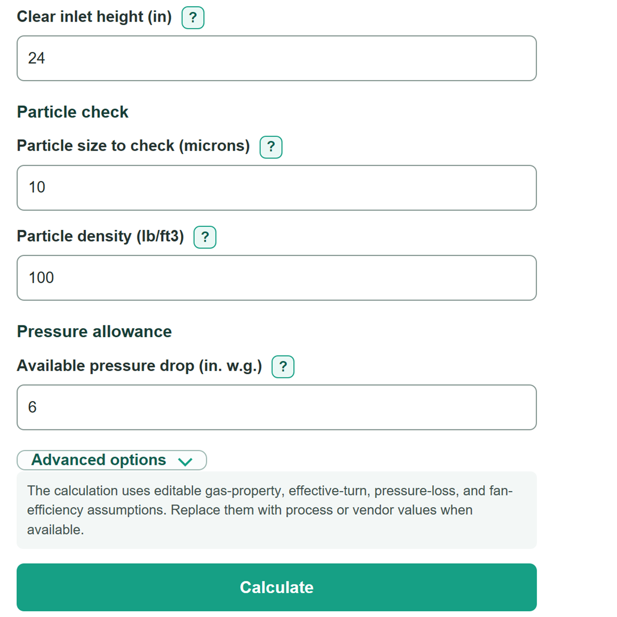
- Copy Clear inlet width (in) and Clear inlet height (in) from the inside of the cyclone inlet, then enter the particle size, particle density, and available pressure allowance.
- Click Calculate. Compare Estimated cyclone pressure drop with Pressure-drop margin; a negative margin means the estimate is above your entered allowance.
- Sanity-check the result by confirming that Airflow at cyclone conditions matches the expected operating flow and that the inlet dimensions are clear internal dimensions, not outside duct dimensions.
Definitions
ACFM: Actual cubic feet per minute, meaning gas volume at the cyclone's operating pressure and temperature.
SCFM: Standard cubic feet per minute, meaning gas volume reported at stated reference conditions. It must be converted to operating flow before calculating cyclone inlet velocity. [1]
D50 cut size: The particle diameter with an estimated 50 percent collection efficiency in this model. A smaller D50 means finer particles are predicted to be collected.
Grade efficiency: The estimated collection percent for one selected particle size. It is not the collection percent for a whole dust mixture.
Pressure drop: The pressure lost as gas passes through the cyclone. This calculator displays the same estimate in inches of water gauge (in. w.g.) and pounds per square inch (psi).
Pressure-drop margin: Available pressure drop minus estimated cyclone pressure drop. A positive margin fits the entered allowance; a negative margin exceeds it.
cP: Centipoise, a unit of dynamic viscosity. Viscosity describes a gas's resistance to flow and affects the cut-size estimate.
Common mistakes and quick fixes
Mistake: Treating a SCFM value as Actual airflow.
Fix: Set Airflow basis to Standard airflow and enter Operating pressure (psig) and Operating temperature (F) .
Mistake: Entering outside duct dimensions for Clear inlet width (in) or Clear inlet height (in) .
Fix: Use the clear internal opening from the cyclone drawing or an inside measurement.
Mistake: Entering the predicted cut size in Particle size to check (microns) .
Fix: Enter the particle size from the lab or material report that you want to evaluate, then compare it with Estimated D50 cut size .
Mistake: Using loose bulk density for Particle density (lb/ft3) .
Fix: Use true particle density from an SDS, supplier data sheet, or lab result. It must be greater than the gas density used by the model.
Mistake: Reading a negative Pressure-drop margin as extra capacity.
Fix: A negative value means Estimated cyclone pressure drop exceeds Available pressure drop (in. w.g.) by that amount.
Mistake: Treating Estimated fan input power for the cyclone drop as total fan power.
Fix: It covers only the calculated cyclone pressure loss, not ducts, hoods, filters, or other system losses.
Limitations & Key Assumptions / Boundary Conditions
- The calculator uses a simplified Lapple-style planning model. It is not a manufacturer rating, a certified design calculation, or a replacement for vendor testing.
- Collection efficiency applies to the one value in Particle size to check (microns). It does not calculate overall collection for a particle-size distribution or dust mass loading.
- Actual airflow uses the entered Gas density at cyclone conditions (lb/ft3). Standard airflow converts the entered SCFM and calculates operating density using ideal-gas behavior, the entered pressure and temperature, and the stated standard reference conditions.
- Results depend strongly on clear inlet dimensions, gas viscosity, particle density, effective gas turns, and the pressure-loss coefficient. Replace the editable air-service assumptions with process or vendor values when available.
- The pressure-drop estimate does not account for all real effects, including inlet and outlet duct losses, dust buildup, erosion, air leaks, unusual geometry, flow swirl, or changing gas composition.
- Estimated fan input power covers only the cyclone pressure loss at the entered airflow and fan efficiency. It excludes other system losses, motor efficiency, operating hours, and electricity cost.
- The calculator blocks nonpositive physical inputs, impossible absolute pressure or temperature, and particle density at or below gas density because those conditions are outside this model.
Methodology
Calculation method
The calculator first finds airflow at cyclone conditions. With Actual airflow, the entered flow is used directly. With Standard airflow, SCFM is adjusted using absolute pressure and absolute temperature. The standard reference is 14.696 psia and 60 F, or 519.67 R. Pressure and gas-flow unit conversions follow NIST guidance [1], and the Fahrenheit-to-Rankine absolute-temperature conversion follows NIST temperature guidance [2].
P_abs = Operating pressure (psig) + 14.696
T_R = Operating temperature (F) + 459.67
ACFM = SCFM * 14.696 / P_abs * T_R / 519.67
Clear inlet width and height are converted from inches to square feet. Inlet velocity is actual airflow per second divided by this clear inlet area.
Inlet area (ft2) = Width (in) / 12 * Height (in) / 12
Inlet velocity (ft/s) = ACFM / 60 / Inlet area (ft2)
The simplified cut-size equation uses gas viscosity, inlet width, effective gas turns, inlet velocity, and the difference between particle and gas density. The result is converted to microns.
D50 (ft) = sqrt(9 * viscosity * inlet width / (2 * pi * turns * inlet velocity * density difference))
Collection (%) = 100 / (1 + (D50 / particle size)^2)
Pressure drop is estimated from inlet velocity pressure multiplied by the entered pressure-loss coefficient. Fan input power is the air power for that estimated cyclone loss divided by fan efficiency.
Pressure drop (psf) = loss coefficient * gas density * inlet velocity^2 / 2
Pressure drop (in. w.g.) = pressure drop (psf) / 5.202083
Fan input power (hp) = pressure drop (psf) * ACFM / 60 / 550 / fan efficiency
Worked example
Using Actual airflow of 5,000 ACFM, a 12 in by 24 in clear inlet, 100 lb/ft3 particle density, 10 micron particles, and the default air-service assumptions gives an estimated D50 of 8.82 microns. The selected-particle collection estimate is 56.26%, pressure drop is 6.26 in. w.g. or 0.226 psi, and the pressure-drop margin against a 6 in. w.g. allowance is -0.26 in. w.g.