
Calculate a power device's steady-state junction temperature, temperature margin, or the heat-sink rating needed for your thermal limit.
Operating conditions
Device limit
Thermal path
Advanced options
Table of contents
How to use our Heat Sink Thermal Resistance and Junction Temperature Calculator
- Choose what you want to calculate: a part without an external heat sink, a part with a heat sink, or the heat-sink rating needed.
- Enter Power dissipated from a loss calculation, simulation, or measurement, then choose W or mW to match the value.
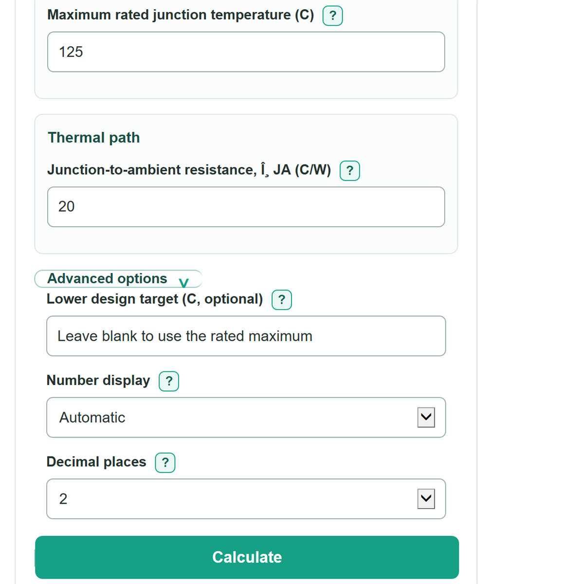
- Enter Worst-case local ambient and Maximum rated junction temperature using the exact device and enclosure conditions.
- For the selected path, copy the applicable thermal resistance values from the device datasheet, interface material data, and heat-sink data. Do not enter theta JA with theta JC, theta CS, and theta SA.
- Check the predicted temperature against Junction-temperature check and Temperature margin below the active limit; a positive margin means the steady-state estimate is below the entered limit.
Definitions
Junction temperature: The estimated temperature inside the semiconductor die, where heat is produced.
Thermal resistance (C/W): How much a part's temperature rises for each watt of heat. Lower C/W means heat can leave more easily.
θJA, junction-to-ambient: A complete device-to-air rating for the stated datasheet board and airflow conditions. It is an alternate path, not an extra resistance to add to a heat-sink stack.
θJC, junction-to-case: Thermal resistance from the semiconductor junction to the specified device case reference point.
θCS, case-to-sink: Thermal resistance through the installed interface between the device case and heat sink, including paste, pad, insulator, mounting force, and contact quality.
θSA, heat-sink-to-ambient: Thermal resistance from the heat sink to surrounding air under stated airflow and installation conditions.
Temperature margin: The active temperature limit minus the predicted junction temperature. A negative margin means the estimate is over the limit.
Common mistakes and quick fixes
Mistake: Entering the load's output power instead of device loss in Power dissipated.
Fix: Enter only the power that becomes heat in the device, from a loss calculation, simulation, or measurement.
Mistake: Using room temperature for Worst-case local ambient when enclosed air near the heat sink is hotter.
Fix: Use the worst expected air temperature at the device or heat sink.
Mistake: Adding Junction-to-ambient resistance, theta JA to the separate heat-sink resistances.
Fix: Use theta JA only for the no-heat-sink path, or use theta JC plus theta CS plus theta SA for the heat-sink path.
Mistake: Copying Heat-sink-to-ambient resistance, theta SA from a rating with different airflow or mounting conditions.
Fix: Match the heat-sink datasheet rating to the planned airflow, orientation, enclosure, and nearby heat sources.
Mistake: Treating Maximum rated junction temperature as a preferred normal operating temperature.
Fix: Enter a lower value in Lower design target (C, optional) when your design needs extra thermal margin.
Mistake: Reading a negative Maximum allowed heat-sink-to-ambient resistance as a heat-sink selection target.
Fix: A negative value means the entered power, ambient temperature, theta JC, and theta CS already use more than the available thermal budget.
Limitations & Key Assumptions / Boundary Conditions
- This is a steady-state model. It estimates temperatures after the thermal path has settled, not short pulses, startup, or changing loads.
- Use power dissipated as heat in the device. Errors in the loss estimate change every temperature result.
- Use local worst-case air temperature near the device or heat sink. Room temperature may be too low for an enclosure.
- For a heat-sink path, theta JC, theta CS, and theta SA are treated as series thermal resistances. Do not combine them with theta JA.
- A heat-sink theta SA value is valid only for its stated airflow, orientation, enclosure, and nearby heat conditions. The calculator does not estimate those conditions.
- Thermal-interface resistance can change with the pad or paste, insulation, mounting hardware, pressure, flatness, and assembly quality.
- The result does not replace device-datasheet limits, thermal testing, or transient thermal-impedance analysis for pulsed operation.
Methodology
Calculation method
The calculator converts power to W and temperatures to C for the calculation. It uses theta JA alone for the no-heat-sink path. For the heat-sink path, it adds theta JC, theta CS, and theta SA as a series path from junction to air. This thermal-network approach uses the temperature rise caused by power passing through thermal resistance. [2]
R total (C/W) = θJA, or θJC + θCS + θSA
Temperature rise (C) = power dissipated (W) * R total (C/W)
Predicted junction temperature (C) = local ambient temperature (C) + temperature rise (C)
The active limit is the lower design target when one is entered; otherwise it is the maximum rated junction temperature.
Temperature margin (C) = active limit (C) - predicted junction temperature (C)
In heat-sink sizing mode, the calculator first finds the total resistance budget, then subtracts the device and interface portions. A negative heat-sink result is retained because it shows that no real nonnegative theta SA can meet the entered target.
Maximum allowed total resistance (C/W) = (active limit (C) - local ambient (C)) / power dissipated (W)
Maximum allowed θSA (C/W) = allowed total resistance - θJC - θCS
Worked example
With 10 W dissipated power, 40 C local ambient, theta JC of 1.5 C/W, theta CS of 0.5 C/W, and theta SA of 6 C/W, total resistance is 8 C/W. The rise is 80 C, so predicted junction temperature is 120 C. With a 150 C limit, the margin is 30 C.
Scope
The model assumes steady power, a stable local ambient temperature, and thermal resistance values that match the actual package, interface, heat sink, airflow, and mounting setup. Fahrenheit entries are converted using the standard C and F relationship; temperature differences convert by the scale factor without adding 32. [1]