
Estimate wire voltage drop, power loss, resistance, and the smallest supported AWG size for your voltage-drop limit.
Advanced options
Table of contents
How to use our Wire Resistance and Power Loss Calculator
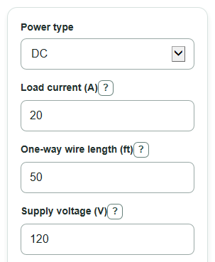
- Choose Power type, then enter Load current, One-way wire length, Supply voltage, Conductor material, and Selected wire size.
- Open Advanced options if you need a different Max voltage drop to allow, Wire temperature, AC power factor, or AC reactance.
- Click Calculate and read the recommended AWG and mm2 cards first, then compare them with your Selected wire size.
- Sanity-check the output: longer wire, higher Load current, warmer Wire temperature, or smaller wire should raise voltage drop and power loss.
Definitions
AWG: American Wire Gauge, a wire-size scale where smaller numbers mean thicker wire. Large sizes such as 1/0, 2/0, and 4/0 are thicker than 1 AWG.
One-way wire length: The distance from the power source to the load. The calculator adds the needed return path in DC and AC single-phase calculations.
Voltage drop: Voltage lost in the wire before power reaches the load. Selected wire voltage drop is shown as a percent of Supply voltage.
Power loss: Electrical power turned into heat in the wire because the conductor has resistance.
Resistance: How strongly the wire opposes current flow. Longer, thinner, or hotter wire has more resistance.
Power factor: For AC circuits, a number from 0 to 1 that describes how much of the current lines up with useful real power.
Reactance: AC opposition caused by magnetic and electric fields around the cable. Leave AC reactance at 0 if you only want a resistance-based estimate.
mm2: Square millimeters, a metric measure of wire cross-sectional area.
Common mistakes and quick fixes
Mistake: Entering round-trip distance in One-way wire length.
Fix: Enter only the source-to-load distance in One-way wire length; the calculator handles the return path for DC and AC single-phase.
Mistake: Treating Selected wire size as bigger when the AWG number is bigger.
Fix: Remember that 10 AWG is larger than 12 AWG, and 1/0 AWG, 2/0 AWG, and 4/0 AWG are larger than 1 AWG.
Mistake: Leaving Supply voltage at 120 V for an AC three-phase circuit that uses a different line-to-line voltage.
Fix: For Power type set to AC three-phase, enter the line-to-line Supply voltage.
Mistake: Using AC power factor or AC reactance to judge a DC circuit.
Fix: For Power type set to DC, those AC inputs are ignored; focus on Load current, One-way wire length, Conductor material, and Selected wire size.
Mistake: Comparing Selected wire voltage drop to the wrong limit.
Fix: Set Max voltage drop to allow to your actual design target, then use the Selected wire size check note.
Mistake: Reading Selected wire power turned into heat as the load's power use.
Fix: Treat Selected wire power turned into heat as wire heating loss only, not the power used by the device.
Limitations & Key Assumptions / Boundary Conditions
- This calculator estimates voltage drop and wire heating. It does not check electrical code, insulation rating, breaker size, conduit fill, terminal temperature rating, or ampacity.
- The supported recommendation scan is limited to 14, 12, 10, 8, 6, 4, 2, 1/0, 2/0, and 4/0 AWG. If none pass, the calculator reports that the tested range is not enough.
- Material constants are fixed for copper and aluminum. Real cable resistance can vary with alloy, strand construction, manufacturing tolerance, and actual operating temperature.
- AC single-phase and AC three-phase voltage drop use a common approximation with power factor and optional reactance. Unbalanced loads, harmonics, motor starting current, and unusual cable layouts can give different results.
- Wire temperature uses a linear correction near ordinary conductor temperatures. Inputs that make the resistance factor zero or negative are outside the model.
- Heat per conductor foot is a rough loss-density number. It is not a safe temperature-rise or ampacity rating.
Methodology
Wire size and area
The calculator converts the selected AWG number to conductor area. For 1/0, 2/0, and 4/0, it uses AWG numbers 0, -1, and -3.
diameter_in = 0.005 * 92^((36 - awg_number) / 39)
area_mm2 = pi * (diameter_in * 25.4)^2 / 4
Resistance at the entered temperature
Resistance is based on resistivity, one-way length, and conductor area. Length is converted from feet to meters, and area is converted from mm2 to m2.
rho_T = rho_20 * (1 + alpha * (temp_c - 20))
R_one_way = rho_T * (one_way_length_ft * 0.3048) / (area_mm2 * 0.000001)
Copper uses rho_20 = 1.7241e-8 ohm m and alpha = 0.00393 per C. Aluminum uses rho_20 = 2.8264e-8 ohm m and alpha = 0.00403 per C.
Voltage drop and power loss
For DC, the calculator doubles one-way resistance because current travels out and back.
V_drop = current_a * 2 * R_one_way
P_loss = current_a^2 * 2 * R_one_way
For AC single-phase, the calculator uses power factor and optional one-way reactance.
sin_phi = sqrt(1 - power_factor^2)
X_one_way = reactance_ohm_per_1000ft * one_way_length_ft / 1000
V_drop = 2 * current_a * (R_one_way * power_factor + X_one_way * sin_phi)
P_loss = current_a^2 * 2 * R_one_way
For balanced AC three-phase, Supply voltage is treated as line-to-line voltage.
V_drop = sqrt(3) * current_a * (R_one_way * power_factor + X_one_way * sin_phi)
P_loss = 3 * current_a^2 * R_one_way
For every power type, the drop percent is calculated from the entered Supply voltage.
drop_percent = 100 * V_drop / supply_voltage_v
Recommended supported wire size
The calculator checks supported sizes from 14 AWG toward 4/0 AWG. It chooses the first supported size where the calculated drop percent is less than or equal to Max voltage drop to allow. It also reports that size's area in mm2. If the selected wire's drop percent is higher than the limit, the status note says the selected size does not meet the limit.
Mini-example
With DC, 20 A, 50 ft one-way, 120 V, copper, 12 AWG, 20 C, and a 3% limit, 12 AWG has about 0.0794 ohm one-way resistance. The round-trip voltage drop is about 3.18 V, so the selected wire voltage drop is about 2.65%. Because 2.65% is below 3%, the supported recommendation can stay at 12 AWG, with an area of about 3.31 mm2.