
Calculate steam turbine power, electric steam rate, required flow, or isentropic efficiency from operating data in familiar US units.
Advanced options
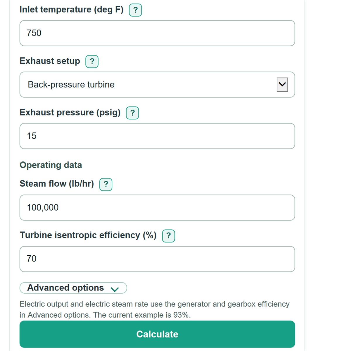
Electric output and electric steam rate use the generator and gearbox efficiency in Advanced options. The current example is 93%.
Table of contents
How to use our Steam Turbine Power and Efficiency Calculator
- Choose the needed result under "Solve for": Power, Steam rate, or Isentropic efficiency.
- Enter the turbine inlet pressure in psig and inlet temperature in deg F from the inlet instrument, DCS record, or datasheet.
- Choose "Exhaust setup." For a back-pressure turbine, enter exhaust pressure in psig; for a condensing turbine, enter a positive condenser vacuum reading in Hg vacuum.
- Enter the fields shown for the selected task, such as Steam flow, Target electric output, or Measured shaft power. Open Advanced options to check or replace Generator and gearbox efficiency (%).
- Click Calculate, then sanity-check that Estimated electric output is lower than Estimated turbine shaft power when generator efficiency is below 100%, and that the pressure drops from inlet to exhaust.
Definitions
Isentropic efficiency: Actual turbine work divided by ideal turbine work for the same inlet state and exhaust pressure. It measures internal steam-expansion performance.
Electric steam rate: Pounds of inlet steam needed to produce one kWh of electric output, in lb/kWh. A lower value means less steam is needed for the same electric energy.
Enthalpy drop: The decrease in steam energy per pound as steam expands through the turbine, shown in Btu/lb. This energy drop produces shaft work.
Ideal isentropic enthalpy drop: The enthalpy drop for an ideal adiabatic expansion with unchanged entropy. It is the reference used to calculate turbine isentropic efficiency.
Vapor quality: The mass percent of vapor in a wet-steam state. A value below 100% means the ideal exhaust includes liquid water droplets.
psig and psia: psig is pressure above local atmospheric pressure; psia is pressure measured from a perfect vacuum. Steam-property calculations require absolute pressure.
Condenser vacuum: A positive vacuum reading in inches of mercury below standard atmospheric pressure. It is not a negative psig entry.
IAPWS-IF97: The International Association for the Properties of Water and Steam formulation used here to calculate water and steam enthalpy, entropy, saturation state, and ideal exhaust state. [1]
Common mistakes and quick fixes
Mistake: Entering absolute pressure in Inlet pressure.
Fix: Enter the gauge reading in psig. The calculator adds standard atmospheric pressure internally.
Mistake: Entering a negative value for Exhaust pressure with a condensing turbine.
Fix: Choose Condensing turbine and enter the vacuum instrument reading as a positive in Hg vacuum value.
Mistake: Using electric generator output as Measured shaft power.
Fix: Use turbine shaft power before generator losses, or calculate shaft power separately using a measured generator efficiency.
Mistake: Mixing a klb/hr reading into Steam flow as though it were lb/hr.
Fix: Multiply klb/hr by 1,000 before entry; for example, enter 100,000 for 100 klb/hr.
Mistake: Treating Turbine isentropic efficiency as Generator and gearbox efficiency (%).
Fix: Keep them separate. Turbine efficiency describes steam expansion, while generator and gearbox efficiency converts shaft power to electric output.
Mistake: Comparing Electric steam rate from two cases with different inlet or exhaust conditions.
Fix: Compare cases only after checking Inlet pressure, Inlet temperature, Exhaust setup, and Exhaust pressure.
Limitations & Key Assumptions / Boundary Conditions
- The model assumes steady flow, one turbine inlet, one exhaust state, and an adiabatic turbine. Heat loss, extraction steam, reheating, bypass flow, leakage, and changing load are not included.
- Inputs must describe ordinary water and steam within the implemented IAPWS-IF97 property range. The calculator blocks unsupported states and inlet conditions that are not suitable for this expansion model.
- Inlet pressure is treated as psig and is converted using standard atmospheric pressure. Actual local atmospheric pressure can differ from the standard reference used for this conversion.
- For condensing service, the vacuum input is referenced to a standard atmosphere. Instrument calibration, noncondensable gases, and local barometric pressure can change the actual exhaust absolute pressure.
- Generator and gearbox efficiency is a separate editable factor. The default is an example planning value, not a rating or guarantee; replace it with test or datasheet data.
- Electric steam rate is a calculated operating estimate, not an acceptance-test result. Equipment limits, steam quality requirements, boiler capacity, piping losses, and condenser capacity still need separate checks.
- In Isentropic efficiency mode, Measured shaft power must be shaft power before generator losses. Inputs that imply more than 100% turbine efficiency are rejected as inconsistent.
Methodology
Steam state and pressure basis
The calculator converts gauge pressures to absolute pressure before finding steam properties. For a condensing turbine, a positive vacuum reading is converted to absolute exhaust pressure. Steam enthalpy, entropy, saturation state, and the ideal isentropic exhaust state use the IAPWS Industrial Formulation 1997 (IAPWS-IF97). [1]
P_abs (absolute pressure) = P_g (gauge pressure) + 14.6959487755 psia
P_exhaust = 14.6959487755 x (1 - vacuum / 29.9212524019) psia
The second formula applies only to a positive condenser vacuum in Hg vacuum. The calculation stops if inlet absolute pressure is not greater than exhaust absolute pressure.
Work and power calculation
The ideal enthalpy drop is inlet enthalpy minus the enthalpy at the exhaust pressure with the same inlet entropy. Actual enthalpy drop equals that ideal drop times turbine isentropic efficiency in Power and Steam rate modes.
Δh_ideal (ideal enthalpy drop) = h_inlet - h_exhaust,ideal
Δh_actual (actual enthalpy drop) = Δh_ideal x turbine efficiency / 100
shaft power (kW) = steam flow (lb/hr) x Δh_actual (Btu/lb) x 0.0002930710701722222
electric output (kW) = shaft power x generator and gearbox efficiency / 100
For steam rate, the calculator divides one kWh by the electric energy produced per pound of steam. Required steam flow equals Target electric output times Electric steam rate.
electric steam rate (lb/kWh) = 1 / (Δh_actual x 0.0002930710701722222 x generator efficiency / 100)
required steam flow (lb/hr) = target electric output (kW) x electric steam rate (lb/kWh)
Efficiency calculation and example
In Isentropic efficiency mode, measured shaft power is first converted to actual work per pound, then compared with the ideal enthalpy drop. Generator efficiency is not used for this turbine-only efficiency result.
turbine isentropic efficiency (%) = 100 x Δh_actual / Δh_ideal
Example: with 600 psig inlet pressure, 750 deg F inlet temperature, 15 psig exhaust pressure, 100,000 lb/hr flow, 70% turbine efficiency, and 93% generator and gearbox efficiency, the calculated ideal drop is about 279.98 Btu/lb. The actual drop is about 195.99 Btu/lb, shaft power is about 5,743.82 kW, electric output is about 5,341.76 kW, and electric steam rate is about 18.72 lb/kWh.
Assumptions and limits
The model uses standard pressure and energy conversions; NIST publishes guidance for SI units and conversions. [2] Results can differ from plant measurements because the model excludes heat loss, pressure loss outside the entered inlet and exhaust states, extraction flow, moisture losses, and instrumentation error. A calculated ideal exhaust quality is shown only when the ideal exhaust state is in the wet-steam region; a superheated state has no vapor-quality percentage.