
Estimate a planning transfer switch amp size from your generator rating, voltage, phase, service path, and optional safety room.
Table of contents
How to use our Generator Transfer Switch Size Calculator
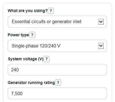
- Choose What are you sizing? as Essential circuits or generator inlet unless the switch sits in the whole-home service path.
- Enter Power type, System voltage, Generator running rating, and Generator rating unit from the generator nameplate or manual.
- Set Could this run near full load for 3 hours or more? to yes when the generator may carry heavy load for a long stretch.
- If you picked whole-home service path, enter Main breaker size so the service-path floor can be checked.
- Use Calculated generator output current and Minimum amps before rounding as a sanity check; if the amps look far too high or low, recheck volts, watts versus kilowatts, and whether you used running rating instead of surge rating.
Definitions
Transfer switch: Equipment that safely switches selected loads between utility power and generator power.
Essential circuits or generator inlet: A setup where the generator feeds selected loads or a panel path that is not carrying the full main service current.
Whole-home service path: A setup where the transfer switch is placed so the home's main service current can pass through it.
System voltage: The line-to-line voltage used for the generator output, such as 240 V, 208 V, or 480 V.
Generator running rating: The power the generator is meant to supply continuously, not the short starting or surge rating.
Continuous-load planning factor: The 1.25 multiplier used here when the load could stay near full load for 3 hours or more.
Minimum amps before rounding: The calculated amp requirement before the calculator moves up to the next supported standard transfer switch size.
Common mistakes and quick fixes
Mistake: Using surge watts in Generator running rating.
Fix: Enter the continuous or running rating in Generator running rating, then choose the matching Generator rating unit.
Mistake: Picking Essential circuits or generator inlet in What are you sizing? when the switch is in the whole-home service path.
Fix: Choose Whole-home service path and enter Main breaker size.
Mistake: Entering 120 in System voltage for a 120/240 V home generator output that is being used at 240 V.
Fix: Use the line-to-line System voltage shown for the generator output, often 240 V for US homes.
Mistake: Leaving Could this run near full load for 3 hours or more? set to no just to get a smaller answer.
Fix: Choose yes when the load could stay near full output for 3 hours or more.
Mistake: Treating Switch size you plan to use as the final approval.
Fix: Check Planned switch room left and Planned switch check, then have an electrician verify the actual equipment and installation.
Limitations & Key Assumptions / Boundary Conditions
- This is a planning size, not a permit-ready electrical design.
- The calculator does not check wire size, breaker type, breaker coordination, neutral switching, grounding, service-entrance listing, AIC, short-circuit current, permits, or local code rules.
- Whole-home service path sizing uses Main breaker size as a floor, so the answer can be larger than the generator-based amps.
- Three-phase results use the balanced three-phase current formula. Uneven loading can change real conductor and equipment needs.
- The supported standard sizes stop at 4000 A. Larger systems need manufacturer or engineering review.
- Have a licensed electrician verify code, service-entrance rating, wiring, breakers, and fault-current details before buying or installing equipment.
Methodology
How the calculator sizes the switch
The calculator first converts the Generator running rating into amps at the entered System voltage and Power type. If Generator rating unit is amps, it uses that amp value directly.
power_watts = generator_rating when the unit is watts
power_watts = generator_rating * 1000 when the unit is kilowatts
calculated_generator_amps = power_watts / voltage for single-phase power
calculated_generator_amps = power_watts / (1.7320508075688772 * voltage) for three-phase power
Next, it applies the selected continuous-load factor and any Extra room above generator amps.
generator_based_amps = calculated_generator_amps * continuous_factor * (1 + extra_room_percent / 100)
The continuous factor is 1.25 when Could this run near full load for 3 hours or more? is set to yes. Otherwise it is 1. For Whole-home service path, the calculator uses the larger of the generator-based amps and Main breaker size.
minimum_required_amps = max(generator_based_amps, main_breaker_amps) for whole-home service path
minimum_required_amps = generator_based_amps for essential circuits or generator inlet
Finally, it rounds up to the first supported standard size: 30, 60, 100, 150, 200, 400, 600, 800, 1000, 1200, 1600, 2000, 3000, or 4000 A.
recommended_switch_size_amps = first standard_size that is at least minimum_required_amps
Planned switch check
If Switch size you plan to use is entered, the calculator compares it with Minimum amps before rounding.
planned_switch_margin_amps = planned_switch_amps - minimum_required_amps
A positive Planned switch room left means the planned switch is above the calculated minimum. A negative value means it is too small by that many amps.
Worked example
For a 7500 W generator on 240 V single-phase power, the calculated current is 7500 / 240 = 31.25 A. If the 125% planning factor is used and extra room is 0%, the minimum is 31.25 * 1.25 = 39.06 A. The next supported standard size is 60 A, so the Recommended standard transfer switch size is 60 A.