
Estimate linear voltage regulator heat, chip temperature, safe load current, efficiency, dropout margin, and heatsink needs from your design values.
Advanced options
Table of contents
How to use our Voltage Regulator Heat Dissipation Calculator
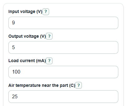
- Enter Input voltage (V), Output voltage (V), and Load current (mA) using worst-case values, not just typical values.
- Enter Air temperature near the part (C) and Thermal resistance, chip to air (C per W) from the regulator datasheet or board estimate.
- Open Advanced options if you know Maximum chip temperature (C), Regulator self-use current (mA), dropout voltage, or heatsink thermal resistance values.
- Click Calculate, then read Total heat the regulator must shed, Estimated chip temperature, and Temperature room left first.
- Sanity-check the result: if Estimated max load current before the heat limit is close to or below your real load current, lower the input voltage, reduce current, improve cooling, or choose a switching regulator.
Definitions
Linear regulator: A regulator that lowers voltage by burning off the extra voltage as heat instead of switching it on and off.
Load current: The current your circuit draws from the regulator output, entered as Load current (mA).
Voltage gap: The difference between Input voltage (V) and Output voltage (V). A bigger gap makes more heat at the same current.
Thermal resistance: Temperature rise per watt of heat flow, shown in C per W. Lower thermal resistance means heat escapes more easily.
Junction temperature: The temperature inside the regulator chip, shown as Estimated chip temperature.
Dropout voltage: The minimum input-to-output voltage gap needed for the regulator to keep the output in regulation.
Quiescent current: Current used by the regulator itself, entered as Regulator self-use current (mA).
Common mistakes and quick fixes
Mistake: Using a typical adapter value for Input voltage (V) when the adapter can run higher with a light load.
Fix: Enter the highest input voltage the regulator may actually see.
Mistake: Entering amps in Load current (mA), such as 0.5 for a 500 mA load.
Fix: Convert amps to milliamps first, so 0.5 A becomes 500 mA.
Mistake: Treating Air temperature near the part (C) as room temperature even when the circuit is inside a warm case.
Fix: Use the air temperature near the board or inside the enclosure.
Mistake: Mixing up Thermal resistance, chip to air (C per W) with Thermal resistance, chip to case (C per W).
Fix: Use chip-to-air for Estimated chip temperature ; use chip-to-case only for the heatsink estimate.
Mistake: Ignoring a negative Voltage gap room left because the heat result looks acceptable.
Fix: Choose a lower output current, lower dropout regulator, or higher input voltage so the regulator can stay regulated.
Mistake: Reading a positive Needed heatsink-to-air thermal resistance as a minimum number.
Fix: Pick a heatsink rating at or below that C per W value; lower C per W means better cooling.
Limitations & Key Assumptions / Boundary Conditions
- This is a steady-state estimate. It does not model short heat pulses, startup surges, changing load current, or thermal shutdown timing.
- The calculation assumes a linear step-down regulator, so Input voltage (V) must be higher than Output voltage (V).
- The result depends strongly on the thermal resistance number. Real board copper area, airflow, enclosure size, mounting, and nearby hot parts can change it.
- Thermal resistance, chip to air (C per W) is used for the main chip temperature estimate. The heatsink estimate uses separate chip-to-case and case-to-heatsink values.
- Maximum chip temperature (C) is a limit from the exact part datasheet. Many designs should stay below the absolute maximum for reliability margin.
- A negative Voltage gap room left means the regulator may not hold the requested output voltage, even if the heat estimate is below the temperature limit.
- Needed heatsink-to-air thermal resistance is a simplified target. Actual heatsinks depend on orientation, airflow, mounting hardware, and nearby surfaces.
Methodology
Core heat calculation
A linear regulator turns the extra voltage between input and output into heat. The main heat term is the voltage gap times the output current [1]. Current is converted from milliamps to amps before watts are calculated.
Iout_A = load_current_ma / 1000
Iq_A = quiescent_current_ma / 1000
voltage_gap_v = vin_v - vout_v
pass_heat_w = (vin_v - vout_v) * Iout_A
self_use_heat_w = vin_v * Iq_A
total_heat_w = pass_heat_w + self_use_heat_w
Thermal check
The chip temperature estimate uses local air temperature plus heat times chip-to-air thermal resistance. Datasheet thermal examples commonly use power dissipation, ambient temperature, maximum junction temperature, and junction-to-ambient thermal resistance in this way [1].
estimated_junction_temp_c = ambient_c + total_heat_w * theta_ja_c_per_w
temperature_margin_c = max_junction_c - estimated_junction_temp_c
Positive temperature room left means the estimate is below the entered chip limit. Negative temperature room left means the estimate is above that limit.
Current, heatsink, efficiency, and dropout
The safe-current estimate solves the same heat equation for load current, then floors the answer at 0 mA because a negative load current is not physical. If self-use heat alone uses the allowed thermal rise, the safe load current is shown as 0 mA.
max_safe_current_ma = max(0, (((max_junction_c - ambient_c) / theta_ja_c_per_w - vin_v * Iq_A) / (vin_v - vout_v)) * 1000)
The heatsink result estimates the heatsink-to-air thermal resistance left after chip-to-case and case-to-heatsink resistance are included. The signed value is kept. A negative result means the chip-to-case and mounting path already use more temperature rise than allowed.
needed_heatsink_theta_sa_c_per_w = (max_junction_c - ambient_c) / total_heat_w - theta_jc_c_per_w - theta_cs_c_per_w
efficiency_percent = (vout_v * Iout_A) / (vin_v * (Iout_A + Iq_A)) * 100
dropout_margin_v = (vin_v - vout_v) - dropout_v
Worked example
With 9 V input, 5 V output, 100 mA load, 25 C air, 65 C per W chip-to-air thermal resistance, 125 C maximum chip temperature, and 0 mA self-use current:
Iout_A is 0.100 A, pass heat is (9 - 5) * 0.100 = 0.400 W, total heat is 0.400 W, estimated chip temperature is 25 + 0.400 * 65 = 51 C, and temperature room left is 125 - 51 = 74 C.