
Convert a fiber report's whole-link ORL or event reflectance into the matching dB form and reflected-power share.
Advanced options
Table of contents
How to use our Optical Return Loss and Reflectance Calculator
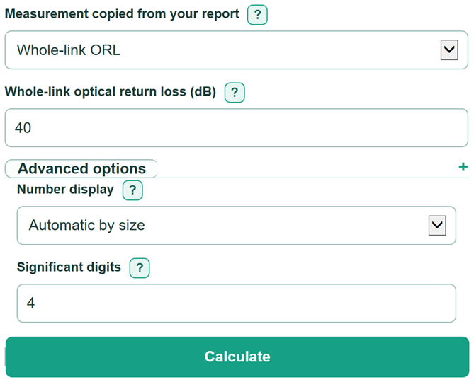
- Choose the report heading that matches the value you copied: Whole-link ORL for a link summary or Individual event reflectance for an OTDR event row.
- Enter Whole-link optical return loss as a positive dB number, or enter Individual event reflectance with its minus sign.
- Choose Number display and Significant digits under Advanced options only if you need a particular reporting format.
- Select Calculate and read the same power ratio in the other dB form, then the reflected power share.
- Sanity-check the direction: a larger positive return-loss value, or a more negative reflectance value, must produce a smaller Reflected power share.
Definitions
Optical return loss (ORL): A positive dB way to state how small the returned optical power is compared with the launched power. Whole-link ORL describes the tested link, not one event.
Event reflectance: A negative dB value for returned power at one localized event, such as a connector, splice, or fiber end.
Decibel (dB): A logarithmic unit for a power ratio. In this calculator, positive return loss and negative reflectance can express the same ratio with opposite signs.
Reflected-to-incident power ratio: Reflected optical power divided by incident optical power. For example, 0.0001 means one ten-thousandth of the incident power is reflected.
Reflected power share: The reflected-to-incident power ratio written as a percent.
Measurement scope: Whether the reported value applies to a whole fiber link or one reflective event. The distinction between link return loss and event reflectance matters in fiber testing. [1]
Common mistakes and quick fixes
Mistake: Entering -40 for Whole-link optical return loss.
Fix: Enter the positive value 40, or switch Measurement copied from your report to Individual event reflectance.
Mistake: Leaving off the minus sign in Individual event reflectance.
Fix: Copy the signed event-table value, such as -40 dB. Use Whole-link optical return loss for a positive return-loss specification.
Mistake: Treating Same power ratio in the other dB form as a measurement of a different scope.
Fix: Use it only as the opposite sign convention for the same ratio. A whole-link ORL result is not a single connector or splice measurement.
Mistake: Reading a smaller positive Whole-link optical return loss as better reflection performance.
Fix: Check Reflected power share: less reflected power means a smaller percentage, a larger positive return-loss value, and a more negative reflectance value.
Mistake: Adding extra Significant digits to make the measurement seem more exact.
Fix: Match Significant digits to the original instrument report or specification. Number display changes appearance, not measurement accuracy.
Limitations & Key Assumptions / Boundary Conditions
- The calculator converts one reported optical power ratio. It does not combine several connector, splice, fiber-backscatter, or end-reflection values into a whole-link ORL result.
- Changing the dB sign does not change measurement scope. A converted whole-link ORL value is still a whole-link value, not the reflectance of one event.
- Results depend on the instrument, test setup, wavelength, launch conditions, fiber condition, and reporting method used to create the copied measurement.
- The supported input range is 0 to 3000 dB for Whole-link optical return loss and -3000 to 0 dB for Individual event reflectance.
- Displayed significant digits format the calculated value only. They cannot recover precision that was not present in the source measurement.
Methodology
Calculation method
The calculator first changes the selected report value into positive return loss. It then uses the base-10 power-ratio relationship to calculate reflected power. Optical return loss and reflectance use opposite dB signs for the same power ratio, while link ORL and event reflectance remain different measurement scopes. [1]
RL (positive return loss in dB) = ORL for Whole-link ORL; RL = -Ref for Individual event reflectance
Other dB form = -RL for Whole-link ORL input; Other dB form = RL for Individual event reflectance input
Reflected-to-incident power ratio = 10^(-RL / 10)
Reflected power share (percent) = 100 * reflected-to-incident power ratio
Worked example
For a Whole-link optical return loss of 40 dB, the other dB form is -40 dB. The power ratio is 10^(-40/10) = 0.0001, and the reflected power share is 0.01%.
Assumptions and limits
The calculation assumes the entered dB value describes a power ratio and follows the stated positive ORL or negative event-reflectance convention. It uses only the visible mode-specific input, accepts decimal dB values, and does not calculate RF mismatch quantities, Fresnel interface behavior, or raw optical power from watts, milliwatts, or dBm.