
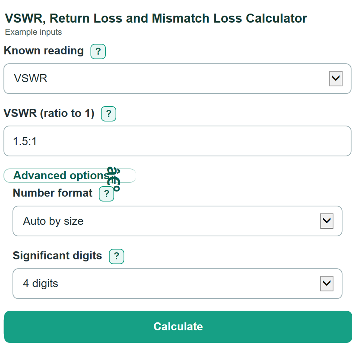
Enter one RF mismatch reading to convert VSWR, return loss, reflection coefficient, mismatch loss, and mismatch-only power percentages.
Advanced options
Table of contents
How to use our VSWR, Return Loss and Mismatch Loss Calculator
- Choose the label that matches your source under Known reading.
- Enter the one visible value. For VSWR (ratio to 1), you can type 1.5 or 1.5:1. For Return loss (dB), enter a positive value such as 20 if an S11 trace shows -20 dB.
- Click Calculate to see the equivalent ratio, dB values, and mismatch-only power percentages.
- Sanity-check the direction: a value closer to 1:1 should have higher Positive return loss, lower Power lost to mismatch, and less Incident power reflected by mismatch.
Definitions
VSWR: Voltage standing wave ratio. It is written as a ratio to 1, such as 1.5:1. An ideal match is 1:1.
Positive return loss: A positive dB measure of how little signal is reflected. Higher positive return loss means a better match. An S11 trace displayed as -20 dB corresponds to 20 dB return loss. [1]
Reflection coefficient magnitude: The size of the reflected wave divided by the size of the incident wave. It has no unit and ranges from 0 to less than 1. Phase is not used here.
Mismatch loss: The dB reduction in accepted power caused by reflection at a mismatch. It does not include cable insertion loss or antenna efficiency.
Incident power reflected by mismatch: The percentage of incident power sent back by the mismatch.
Incident power accepted after mismatch: The percentage of incident power that is not reflected at the measurement plane.
Common mistakes and quick fixes
Mistake: Typing 1.5:2 in VSWR (ratio to 1) .
Fix: Use a number such as 1.5 or the standard form 1.5:1. The ratio denominator must be 1.
Mistake: Entering -20 dB in Return loss (dB) because an analyzer shows S11 = -20 dB.
Fix: Enter positive 20 dB. This field uses positive return loss, not the signed S11 trace value.
Mistake: Entering 1 or a larger number for Reflection coefficient magnitude (unitless) .
Fix: Enter a magnitude from 0 to less than 1. A value of 1 would make the finite VSWR conversion impossible.
Mistake: Adding cable loss to Mismatch loss (dB) .
Fix: Enter only loss caused by reflected power. Cable insertion loss and antenna efficiency are separate effects.
Mistake: Treating Incident power accepted after mismatch as antenna radiation efficiency.
Fix: Read it only as power not reflected at the measurement plane. It does not include later system losses.
Limitations & Key Assumptions / Boundary Conditions
- The calculator uses only the magnitude of the reflection coefficient. It does not calculate S11 phase, complex impedance, or impedance transformations.
- Reflected and accepted power percentages describe mismatch at the measurement plane only. They exclude cable and connector loss, antenna radiation efficiency, amplifier behavior, and other system losses.
- Return loss is entered as a positive value. If an instrument displays S11 as a negative dB trace, enter its positive magnitude instead.
- An ideal match has reflection coefficient 0 and VSWR 1:1. Its return loss is shown as an infinite limit rather than a finite number.
- Displayed digits are formatting choices. They cannot make a source measurement more accurate than the instrument or datasheet value.
Methodology
Conversion method
The calculator first converts the selected reading into reflection coefficient magnitude, shown as Γ. It then calculates every other scalar mismatch measurement from Γ. These are standard relationships for VSWR, reflection coefficient, return loss, and mismatch loss. [2]
Γ = (VSWR - 1) / (VSWR + 1)
Γ = 10^(-return loss / 20)
Γ = sqrt(1 - 10^(-mismatch loss / 10))
VSWR = (1 + Γ) / (1 - Γ)
return loss (dB) = -20 log10(Γ)
reflected power (%) = 100 x Γ^2
mismatch loss (dB) = -10 log10(1 - Γ^2)
accepted power (%) = 100 x (1 - Γ^2)
Worked example
For VSWR 2:1, Γ is 1/3, or about 0.3333. The reflected-power share is about 11.11%, accepted power is about 88.89%, return loss is about 9.542 dB, and mismatch loss is about 0.5115 dB. The calculator uses stable logarithm and exponential forms near an ideal match to reduce rounding error.