
Enter your cable datasheet loss, route length, and input power to estimate power reaching the antenna feed point.
Advanced options
Installed losses
Result format
Calculation details
Table of contents
How to use our Coaxial Cable Loss and Power-at-Antenna Calculator
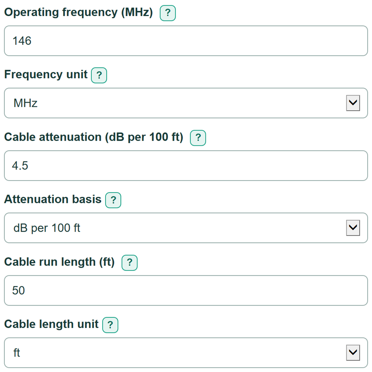
- Set Frequency unit, then enter Operating frequency (MHz) from your radio, channel plan, or equipment settings.
- Copy the exact cable's loss at that frequency into Cable attenuation (dB per 100 ft), and choose the matching Attenuation basis.
- Measure the whole cable route for Cable run length (ft), including rises, bends, and service loops, then enter Power entering the coax (W).
- Open Advanced options only if you have documented losses for connectors, adapters, arrestors, filters, splitters, or other inline devices.
- Click Calculate and compare Cable-only loss for this run with Entered installed-component loss. Check that the attenuation value came from the same frequency or the nearest documented datasheet row.
Definitions
Attenuation: Signal loss along a cable. Cable documentation commonly states it in dB per 100 ft or dB per 100 m at a stated frequency.
dB: Decibels, a logarithmic way to express a power ratio. Positive loss values are added along the feedline. [1]
dBm: A power level referenced to 1 milliwatt. For example, 30 dBm equals 1 W and 40 dBm equals 10 W.
Insertion loss: Power loss caused by a component placed in the RF path, such as a connector, adapter, arrestor, filter, or splitter.
Matched feedline: A feedline with no modeled mismatch loss from SWR. This calculator uses that assumption.
Antenna feed point: The connection where the coax attaches to the antenna. Power at this point is not the same as radiated power.
Common mistakes and quick fixes
Mistake: Entering radio rated power instead of Power entering the coax (W) .
Fix: Use the power at the start of the modeled cable, after any device installed before that cable.
Mistake: Copying Cable attenuation (dB per 100 ft) from a different frequency or a similar-looking cable.
Fix: Use documentation for the exact cable at Operating frequency (MHz) , or the nearest listed frequency.
Mistake: Choosing dB per 100 ft when the datasheet value is actually per 100 m.
Fix: Set Attenuation basis to the same distance basis printed beside the datasheet value.
Mistake: Measuring only the straight-line distance for Cable run length (ft) .
Fix: Include the full installed route, vertical sections, bends, and any service loop.
Mistake: Entering only Connector or adapter count without Loss per connector or adapter (dB) .
Fix: Enter both values from the component documentation, or clear both fields if connector loss is unknown.
Mistake: Reading Estimated power at the antenna feed point as radiated power.
Fix: Treat it as power arriving at the antenna input; antenna efficiency, gain, and mismatch are separate effects.
Limitations & Key Assumptions / Boundary Conditions
- The calculation assumes a matched feedline. It does not estimate extra loss from SWR, impedance mismatch, reflections, or an improperly tuned antenna.
- The entered cable attenuation must be from the exact cable documentation at the operating frequency or the nearest documented frequency. The calculator does not interpolate or create a cable loss value.
- Cable loss is treated as proportional to cable length at the entered frequency.
- Results exclude antenna gain, antenna efficiency, radiated power, and receiver performance.
- Temperature, cable aging, water ingress, crushed cable, poor terminations, and undocumented installation damage can make real loss higher than the estimate.
- Optional connector and device losses are included only when entered. Blank optional fields add 0 dB.
Methodology
Calculation method
The calculator first converts the entered length to feet, attenuation to dB per 100 ft, and input power to watts when needed. It uses the entered frequency to identify the datasheet row you selected; frequency does not create or adjust an attenuation value.
cable loss (dB) = attenuation (dB per 100 ft) x cable length (ft) / 100
Connector loss is included only when both connector fields are completed. Other installed device loss is a separate entered total.
connector loss (dB) = connector or adapter count x loss per connector or adapter (dB)
total feedline loss (dB) = cable loss + connector loss + other installed device loss
Decibel losses add directly. The calculator converts total loss to the fraction of input power that remains using the standard power-ratio relationship. [1]
retained power fraction = 10 ^ (-total feedline loss (dB) / 10)
power at antenna (W) = power entering coax (W) x retained power fraction
power not delivered (W) = power entering coax (W) - power at antenna (W)
Mini-example
A 50 ft cable run with 4.5 dB per 100 ft has 2.25 dB of cable-only loss. With 50 W entering the coax and no optional installed losses, the retained fraction is about 0.5957, so the estimated antenna-end power is about 29.8 W and about 20.2 W is not delivered to the antenna.
Calculation boundaries
This is a matched-feedline estimate. Measured feedline loss can differ because of SWR, cable condition, moisture, connector quality, temperature, and installation details. Feedline-loss measurements can help check an installed system when suitable test equipment is available. [2]