
Estimate line array coverage room, endpoint aim angles, average joint splay, and listener throws from your venue measurements.
Table of contents
How to use our Line Array Splay Angle, Vertical Coverage and Throw Calculator
- Measure the horizontal plan distance from the same array reference point to the nearest and farthest listeners. Enter these as Front row horizontal distance and Back row horizontal distance in decimal feet or feet and inches.
- Enter the expected ear elevations at each endpoint as Front listener height and Back listener height. Use separate values for raked seating.
- Enter the height of the acoustic or aiming point as Array aiming reference height. Do not substitute fly-frame trim unless it is the same point.
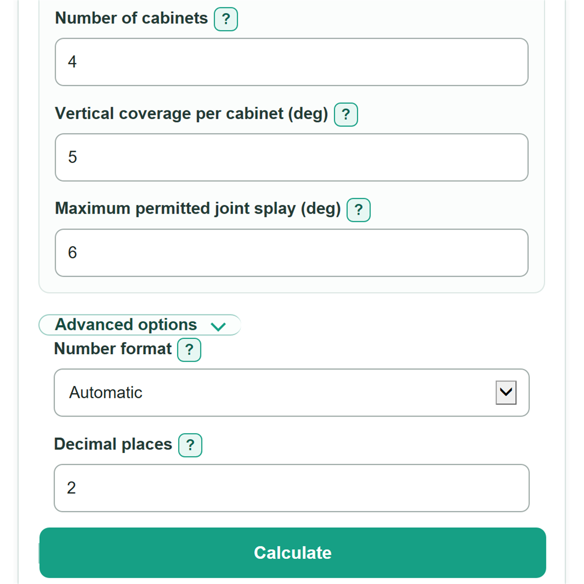
- Copy Number of cabinets, Vertical coverage per cabinet, and Maximum permitted joint splay from the planned system and its manufacturer documentation.
- Click Calculate. Check that estimated coverage room is positive and that the suggested average joint splay does not exceed your entered permitted maximum; then verify the final design in manufacturer prediction and rigging software.
Definitions
Array aiming reference height: The height of the chosen acoustic or aiming point above the same floor or elevation reference used for listener heights.
Horizontal plan distance: The level, map-like distance from the array reference point to a listener, not the distance along a sloped floor.
Vertical coverage per cabinet: The nominal up-and-down coverage angle listed for one loudspeaker enclosure. It is separate from mechanical joint splay.
Joint splay: The angle opened between two neighboring cabinets. The maximum permitted value must come from documentation for the exact loudspeaker and hardware.
Required vertical coverage: The angle between the sight lines from the array reference point to the front and back listener endpoints.
Throw: The straight-line geometric distance from the array reference point to a listener. It does not predict sound level.
Common mistakes and quick fixes
Mistake: Measuring Front row horizontal distance along a sloped floor.
Fix: Measure the horizontal plan distance from the array reference point to the listener location.
Mistake: Using one value for Front listener height and Back listener height in raked seating.
Fix: Enter the expected ear height at each endpoint from the same elevation reference.
Mistake: Entering fly-frame trim as Array aiming reference height when the aiming point is lower.
Fix: Use the acoustic or aiming reference point used for this geometry check.
Mistake: Entering the horizontal specification from a 90 x 5 deg speaker rating as Vertical coverage per cabinet.
Fix: Enter the vertical value, which is 5 deg in a 90 x 5 deg rating.
Mistake: Treating Suggested average joint splay as an approved cabinet-by-cabinet rigging schedule.
Fix: Use it only as a preliminary average, then follow the exact manufacturer rigging chart and prediction software.
Mistake: Entering 12 or more inches in a feet-and-inches measurement.
Fix: For Array aiming reference height and other ft fields, use inches from 0 to less than 12, or convert to decimal feet.
Limitations & Key Assumptions / Boundary Conditions
- This is a preliminary 2D geometry calculation. It does not model horizontal coverage, room shape, balcony overhangs, reflections, delay fills, or audience areas between the two endpoints.
- A positive estimated coverage room means the entered simplified vertical window is wider than the endpoint angle. It does not prove even level, frequency response, tonal consistency, or intelligibility.
- The available vertical window uses nominal vertical coverage plus maximum permitted splay across all joints. Real arrays can require a nonuniform joint schedule and manufacturer-specific constraints.
- The suggested average joint splay is not a rigging approval, load calculation, or manufacturer-approved per-cabinet schedule.
- The downward-aim workflow requires the array aiming reference height to be at or above both listener heights. It is not designed for targets above that reference point.
- Results depend on measurements being referenced to the same point and elevation datum. A wrong reference height or sloped-distance measurement can change the angles substantially.
Methodology
Geometry calculation
All distance and height entries are converted to decimal feet. A value such as 15 ft 6 in becomes 15.5 ft. The calculator finds a downward sight-line angle from the array aiming reference point to each listener endpoint.
front aim = atan2(array reference height - front listener height, front row horizontal distance) x 180 / pi
rear aim = atan2(array reference height - back listener height, back row horizontal distance) x 180 / pi
The required vertical coverage is the absolute difference between those two endpoint angles. This allows the rear listener to be higher or lower than the front listener.
required vertical coverage = abs(front aim - rear aim)
The simplified available vertical window starts with one cabinet's nominal vertical coverage and adds the entered maximum joint splay for every joint. A hang with N cabinets has N - 1 joints.
available vertical window = vertical coverage per cabinet + (number of cabinets - 1) x maximum permitted joint splay
estimated coverage room or shortfall = available vertical window - required vertical coverage
A positive coverage value is estimated room; a negative value is an estimated shortfall. The suggested average joint splay divides only the extra angle needed beyond one cabinet's nominal coverage across the available joints. It is set to 0 when one cabinet's nominal coverage already spans the endpoint window.
suggested average joint splay = max(0, (required vertical coverage - vertical coverage per cabinet) / (number of cabinets - 1))
Each throw is the straight-line distance formed by the horizontal distance and vertical drop.
throw = sqrt(horizontal distance^2 + vertical drop^2)
Worked example
With a 20 ft array reference height, a front listener at 15 ft away and 8 ft high, and a rear listener at 40 ft away and 5 ft high, the front aim is about 38.66 deg and the rear aim is about 20.56 deg. The required vertical coverage is about 18.10 deg. Four cabinets with 5 deg nominal vertical coverage and 6 deg maximum joint splay produce a simplified 23 deg window, or about 4.90 deg of estimated coverage room.
Calculation boundaries
The calculator blocks a back row that is not farther than the front row, an array reference below either listener, fewer than two cabinets, invalid feet-and-inches text, negative distances, nonpositive nominal coverage, and negative maximum joint splay. It keeps the full calculation precision internally; the Number format and Decimal places controls change display only.