
Estimate hydraulic waste heat, reservoir cooling, and preliminary oil-cooler duty from heat data, motor power, an oil warm-up test, or pressure drop and flow.
Advanced options
This is a constant-coefficient heat-balance extrapolation, not a predicted or safe operating temperature. Real oil properties and heat loss change with temperature. Assess cooling at your target temperature and follow the fluid and equipment temperature limits.
Calculation details
Table of contents
How to use our Hydraulic Heat Load and Oil Cooler Size Calculator
- Choose how you will find the heat load, then enter only the measurements shown for that method.
- Enter Reservoir capacity, Highest surrounding air temperature, and Target oil temperature from the machine and installation conditions.
- Open Advanced options if you know the exposed reservoir area, need a different heat-transfer estimate, or want to change the extra cooler capacity.
- Click Calculate and use Preliminary oil-cooler duty as the starting heat duty for a cooler supplier.
- Sanity-check
Estimated reservoir heat rejection at target temperature
againstCalculated hydraulic heat load
. TheTheoretical no-cooler temperature (simplified model)
is an extrapolation of the same constant heat-transfer assumption, not an operating-temperature prediction.
Definitions
Hydraulic heat load: Waste energy changed into heat in hydraulic oil, measured here in BTU/hr.
Pressure drop: The pressure decrease across a valve, restriction, or flow path. Pressure drop is different from the machine's full system pressure.
Reservoir heat rejection: Heat that the outside of the tank can release to cooler surrounding air at the target oil temperature.
Exposed reservoir area: Tank surface area open to the surrounding air. Insulated or blocked surfaces should not be counted.
Heat-transfer estimate: An editable simplified value that relates reservoir area and oil-to-air temperature difference to heat rejection.
Cooler duty: The heat an external oil cooler must reject after the estimated reservoir heat rejection and selected extra capacity are included.
Specific heat: Heat needed to raise one pound of oil by 1 F. It is used only by the warm-up test method.
Common mistakes and quick fixes
Mistake: Entering full system pressure as Pressure drop through the heat-producing path.
Fix: Enter pressure before the loss-producing part minus pressure after it, and pair it with Flow through the heat-producing path.
Mistake: Using nominal Reservoir capacity as Oil volume heated during the test without checking the actual oil volume.
Fix: Enter the oil volume that actually warmed in the reservoir and connected circuit during the test.
Mistake: Running a warm-up test with an external cooler operating.
Fix: Turn the external cooler off for the test, then enter Oil temperature at test start, Oil temperature at test end, and Warm-up test time.
Mistake: Treating Known heat load as useful hydraulic output.
Fix: Enter only waste heat added to the oil in BTU/hr.
Mistake: Assuming Reservoir capacity proves the tank's cooling area.
Fix: Use Known exposed reservoir area (sq ft) when a drawing or measurement is available; otherwise treat the capacity-based area as an estimate.
Mistake: Selecting a catalog cooler using Preliminary oil-cooler duty alone.
Fix: Give the supplier the duty plus oil flow, oil viscosity, oil temperature, allowable pressure drop, and cooling-air or water conditions.
Limitations & Key Assumptions / Boundary Conditions
- This is a preliminary steady heat-balance estimate. It does not model changing loads, duty cycles, multiple loss paths, warm-up transients, or thermostat control.
- Reservoir capacity is converted to an estimated top-and-side area only when Known exposed reservoir area (sq ft) is blank. Real tank shape, mounting, paint, insulation, and airflow can change heat rejection substantially.
- The measured warm-up method assumes the external cooler is off, the entered oil volume warmed together, and oil density and specific heat stay reasonably constant over the test.
- The pressure-flow method assumes hydraulic power lost across the entered path becomes heat. Use the pressure drop and flow through the same path.
- A zero Preliminary oil-cooler duty means the simplified reservoir estimate can reject the calculated heat at the stated target temperature. It does not prove that an external cooler is unnecessary in all operating conditions.
- Final cooler selection needs manufacturer performance data plus oil flow, oil type and viscosity, allowable oil-side pressure drop, oil inlet temperature, and the actual air or water cooling conditions.
Methodology
Calculation method
The selected heat-source method first produces Calculated hydraulic heat load. Known heat load is used directly. The motor method converts the entered share of installed motor power to heat. The warm-up method calculates the heat absorbed by the entered oil volume over the test time. The pressure-flow method converts hydraulic power lost through the stated path into heat.
motor heat = installed motor power x (estimated power changed to heat / 100) x 2544.43
warm-up heat = oil volume x oil density x oil specific heat x (end temperature - start temperature) x 60 / warm-up test time
pressure-flow heat = (pressure drop x path flow / 1714) x 2544.43
If Known exposed reservoir area (sq ft) is blank, the calculator estimates the exposed top and four sides from reservoir capacity. A direct entered area replaces that estimate.
estimated reservoir area = 5 x (reservoir capacity / 7.48052)^(2/3)
The reservoir model credits heat rejection only when Target oil temperature is above Highest surrounding air temperature.
reservoir heat rejection = heat-transfer estimate x reservoir area x max(0, target oil temperature - surrounding air temperature)
The remaining heat is increased by Extra cooler capacity (percent). The external cooler duty cannot go below zero.
preliminary cooler duty = max(0, heat load - reservoir heat rejection) x (1 + extra cooler capacity / 100)
cooler duty in kW = preliminary cooler duty / 3412.142
The no-cooler calculation solves heat load = heat-transfer estimate x area x (oil temperature - surrounding air temperature), keeping the heat-transfer estimate constant. Extreme results show the limits of that extrapolation; they do not establish a safe or attainable oil temperature.
theoretical no-cooler temperature = surrounding air temperature + heat load / (heat-transfer estimate x reservoir area)
Worked example
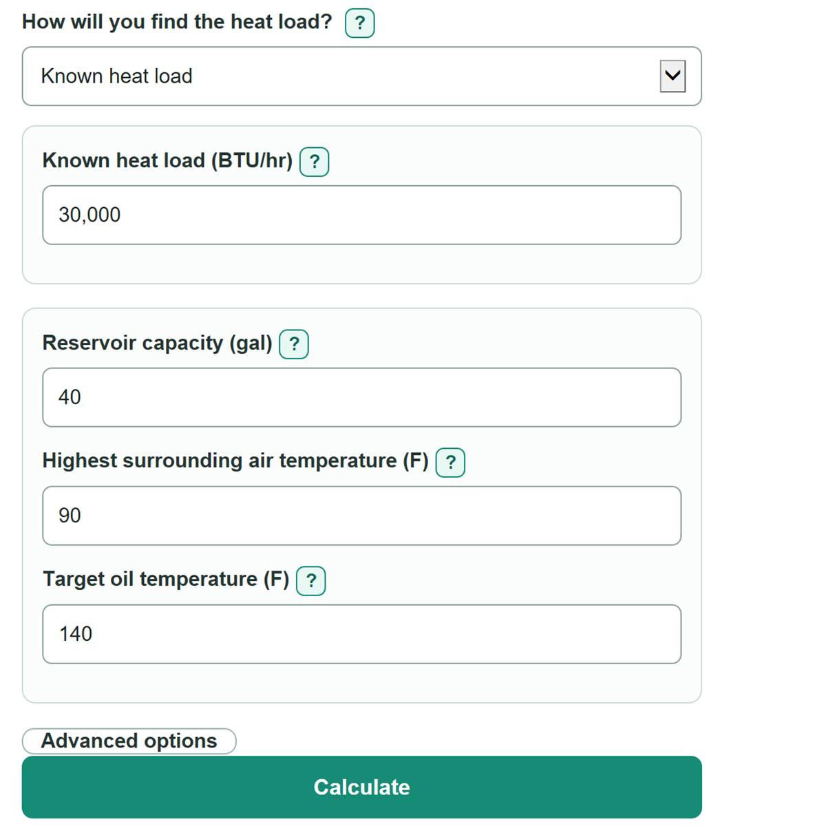
With a known heat load of 30,000 BTU/hr, a 40 gal reservoir, 90 F surrounding air, 140 F target oil temperature, a 2.5 BTU/hr per sq ft per F heat-transfer estimate, and 20% extra capacity, the fallback area is about 15.29 sq ft. Estimated reservoir heat rejection is about 1,911 BTU/hr, so preliminary cooler duty is about 33,707 BTU/hr, or 9.88 kW.
What the math holds constant
The model treats the heat load and surrounding air temperature as steady. It uses editable oil properties and a simplified reservoir heat-transfer estimate. Unit conversions for gallons, horsepower, and kilowatts follow standard unit-conversion practice. [1]