
Correct an uncorrected thermal-camera reading for surface emissivity and reflected apparent temperature in Fahrenheit or Celsius.
Advanced options
Table of contents
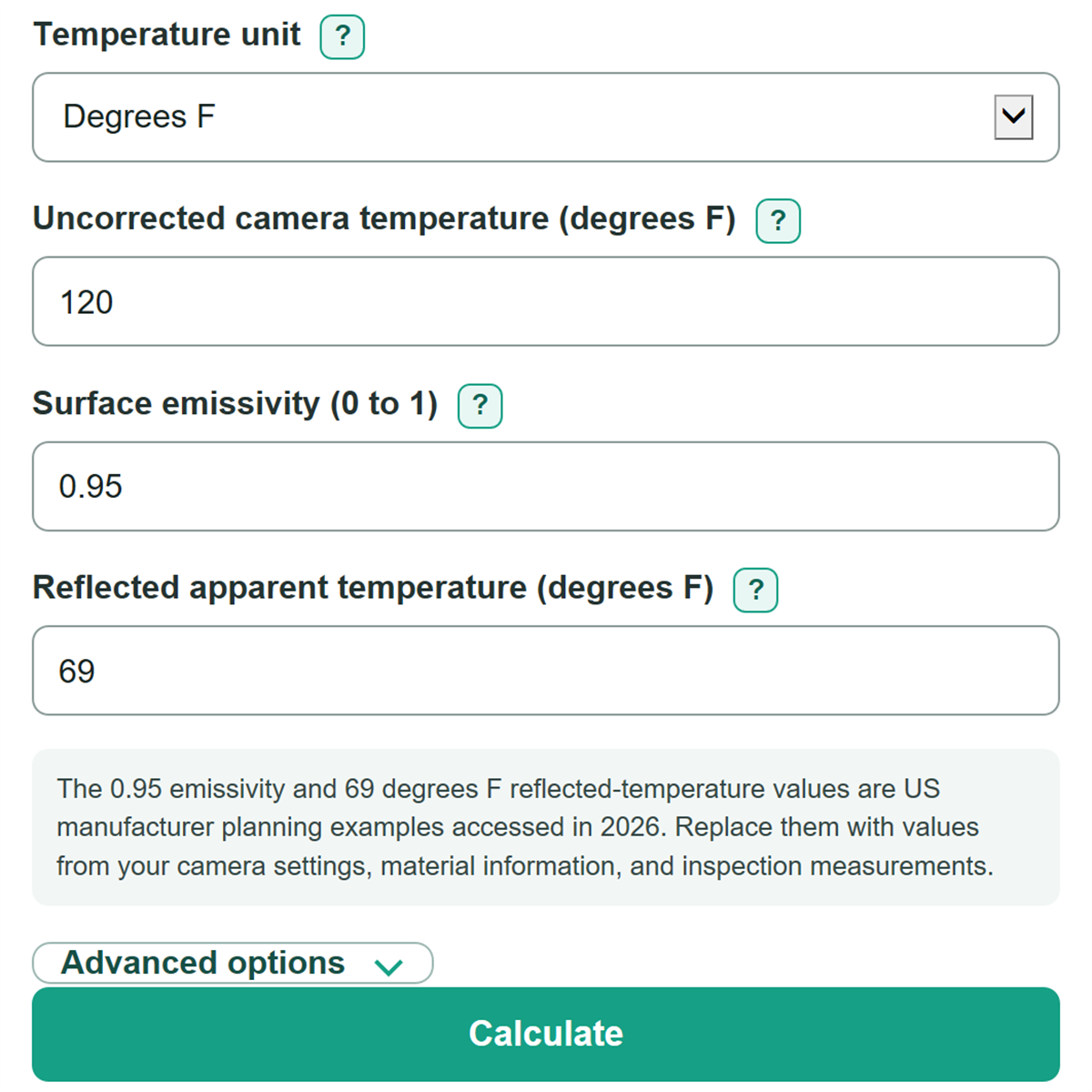
How to use our Thermography Emissivity Correction Calculator
- Choose Temperature unit to match the camera display, radiometric file, or inspection report.
- Enter the Uncorrected camera temperature before camera emissivity and reflected-temperature corrections were applied.
- Enter Surface emissivity as a decimal such as 0.95, or type an explicit percent such as 95%.
- Enter Reflected apparent temperature from your inspection method, then select Calculate.
- Check that the temperature change and reflected share make sense for the surface. A low-emissivity target or a large reflected share means the reflected-temperature measurement has more effect on the estimate.
Definitions
Surface emissivity: A number from greater than 0 to 1 that describes how strongly a surface emits thermal radiation. A value near 1 means less of the detected signal is modeled as reflection.
Uncorrected camera temperature: The apparent temperature read from a thermal camera before emissivity and reflected-temperature correction.
Reflected apparent temperature: The apparent temperature of thermal radiation from the surroundings that reflects off the target toward the camera. It is not automatically the air temperature.
Kelvin: An absolute temperature scale used in the fourth-power calculation. Zero Kelvin is absolute zero.
Estimated reflected share of camera signal: The modeled percentage of the camera signal attributed to reflected radiation rather than emission from the target surface.
Common mistakes and quick fixes
Mistake: Entering 95 in Surface emissivity.
Fix: Enter 0.95, or add the percent sign and enter 95%.
Mistake: Copying a camera reading that was already corrected in the camera settings into Uncorrected camera temperature.
Fix: Use an uncorrected apparent reading, or do not run this correction again.
Mistake: Using room-air temperature as Reflected apparent temperature without measuring the reflected scene.
Fix: Use the reflected-temperature method in your camera or site procedure; the reflected scene can differ from room air.
Mistake: Choosing Degrees F in Temperature unit while copying values recorded in degrees C.
Fix: Set Temperature unit to the unit used by both temperature values before entering them.
Mistake: Treating Estimated reflected share of camera signal as an accuracy rating.
Fix: Read it only as the modeled portion caused by reflected radiation, not as camera uncertainty.
Limitations & Key Assumptions / Boundary Conditions
- This is a simplified opaque-surface radiative estimate. It does not include atmospheric-path loss, humidity, object distance, external IR windows, optics transmission, or camera calibration error.
- Use only an uncorrected apparent camera reading. Applying this calculation to a reading already corrected by camera settings can double-correct it.
- Emissivity can change with material, coating, oxidation, surface finish, viewing angle, and condition. A table value may not match the inspected surface.
- Low-emissivity surfaces are more sensitive to Reflected apparent temperature. A small error in that measurement can cause a large change in the corrected estimate.
- The model requires physically possible inputs. Temperatures at or below absolute zero and combinations that create a negative fourth-power balance are rejected.
Methodology
Calculation method
The calculator first converts both entered temperatures to Kelvin because thermal radiation is modeled with absolute temperature raised to the fourth power.
T_camera,K = (T_camera,F - 32) * 5/9 + 273.15
T_reflected,K = (T_reflected,F - 32) * 5/9 + 273.15
For Celsius entries, the calculator adds 273.15 directly. It then uses emissivity, written as ε, to separate modeled emitted and reflected radiation.
T_corrected,K = ((T_camera,K^4 - (1 - ε) * T_reflected,K^4) / ε)^(1/4)
It converts the corrected Kelvin temperature back to the selected unit and keeps the change from the camera reading signed.
Temperature change = corrected surface temperature - uncorrected camera temperature
The reflected share is the reflected fourth-power contribution divided by the total fourth-power signal represented by the camera reading.
Reflected share (%) = 100 * (1 - ε) * T_reflected,K^4 / T_camera,K^4
Worked check
If the uncorrected camera temperature and Reflected apparent temperature are both 100 degrees F and Surface emissivity is 0.95, the corrected surface temperature remains 100 degrees F. The modeled reflected share is 5%, and the temperature change is 0 degrees F.
What the model leaves out
The calculation assumes an opaque surface and a direct radiative path. FLIR measurement guidance lists emissivity and reflected temperature among measurement values; the editable defaults are planning examples, not values to assume for every inspection. Replace them with your camera settings, material information, and inspection measurements. [1]