
Estimate an extension cord’s load and voltage drop, or calculate a planning watt limit from the entered ratings. This does not establish that a cord setup is safe.
Table of contents
How to use our Extension Cord Wattage Calculator
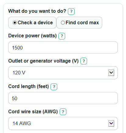
- Choose What do you want to do?: use Check a device if you know the device watts, or Find cord max if you want the calculated planning limit.
- Enter Device power (watts) when checking a device, then choose Outlet or generator voltage (V).
- Enter Cord length (feet), choose Cord wire size (AWG), and enter the smaller number from Cord tag or outlet limit (amps).
- Open Advanced options if the load runs 3 hours or more, if you want a stricter Voltage drop limit (percent), or if you know Motor starting pull (times running amps).
- Use Calculated watt limit, Within calculated limits?, and What limited the answer together, then sanity-check that the cord tag, outlet, plug, and device label all agree with the setup.
Definitions
Watts: Power used by the device. A higher watt number usually means the cord must carry more current.
Amps: The amount of electric current flowing through the cord. More amps make voltage drop and heating more important.
Volts: Electric pressure from the outlet or generator. Regular US household outlets are commonly 120 V, while some large equipment uses 240 V.
AWG: American Wire Gauge, the wire size system used for many cords. A smaller AWG number means thicker wire.
Voltage drop: Voltage lost as electricity travels through the cord. Long cords, thin wires, and high amps increase this loss.
Calculated watt limit: The lowest modeled limit from the entered amp rating, wire-size planning cap, runtime setting, and voltage-drop target. Cord condition and installation are not assessed.
Motor starting pull: A short burst of extra current some motors need when they start, often higher than the running current.
Common mistakes and quick fixes
Mistake: Using the breaker size for Cord tag or outlet limit (amps) when the cord tag or plug shows a smaller number.
Fix: Enter the smallest amp number from the cord tag, plug, outlet, generator outlet, or breaker.
Mistake: Entering one-way wire path math in Cord length (feet) by doubling the cord length yourself.
Fix: Enter the physical cord length only; the calculator counts the out-and-back wire path.
Mistake: Picking a larger Cord wire size (AWG) number because it sounds stronger.
Fix: Remember that a smaller AWG number is thicker wire, so 12 AWG is thicker than 16 AWG.
Mistake: Leaving How long will it run? on less than 3 hours for a heater, pump, charger, or lights that run for many hours.
Fix: Choose 3 hours or more so Calculated watt limit uses the lower long-run planning limit.
Mistake: Treating a positive Watts left or over as approval for a damaged, coiled, covered, indoor-only, or permanent cord setup.
Fix: Read Safety note and use only an undamaged cord that is rated for the location and type of use.
Limitations & Key Assumptions / Boundary Conditions
- This calculator is a planning check, not approval for unsafe use. It does not approve damaged cords, hot cords, cords under rugs, coiled cords under load, indoor cords outdoors, cords through walls, or permanent wiring.
- The result depends on the number entered for Cord tag or outlet limit (amps). If the cord, plug, outlet, generator outlet, breaker, or device manual gives a lower limit, use the lower limit.
- Resistance values are approximate copper conductor values near room temperature. Real cords can vary because of temperature, connector condition, conductor material, and manufacturing differences.
- The wire-size planning amp caps are planning caps only. A listed cord assembly can have a lower rating than the wire size alone suggests.
- The voltage-drop estimate uses a simple round-trip cord path. It does not model power factor, motor behavior after startup, connector heating, reel temperature rise, or voltage changes at the outlet.
- The 3 hours or more setting applies a 0.8 factor to the base amp cap. Some devices or job sites may require stricter rules.
- For motor loads, Estimated start voltage is only a rough check. A motor may still fail to start if its design, load, or supply voltage needs more current than entered.
Methodology
How the calculator checks the cord
The calculator first turns device watts into current when you use Check a device.
load_amps = load_watts / source_voltage
It then estimates the round-trip resistance of the extension cord. The 2 in the formula counts current going out to the device and returning through the cord.
cord_resistance_ohms = resistance_ohms_per_1000_ft[cord_gauge_awg] * (2 * cord_length_ft) / 1000
The built-in copper resistance table uses 18 AWG = 6.385, 16 AWG = 4.016, 14 AWG = 2.525, 12 AWG = 1.588, and 10 AWG = 0.999 ohms per 1000 ft. The wire-size planning amp caps are 18 AWG = 10 A, 16 AWG = 13 A, 14 AWG = 15 A, 12 AWG = 20 A, and 10 AWG = 30 A.
Next, it finds the amp limit from heat-related planning checks.
base_amp_cap = min(cord_limit_amps, gauge_planning_amps[cord_gauge_awg])
thermal_amp_cap = base_amp_cap * continuous_factor
The continuous factor is 1 for less than 3 hours and 0.8 for 3 hours or more. The calculator also finds the current limit set by the chosen voltage-drop target.
drop_amp_cap = (source_voltage * drop_limit_percent / 100) / cord_resistance_ohms
The calculated amp limit is the lower of the heat-related planning limit and the voltage-drop limit. The calculated watt limit is voltage times that amp limit.
max_safe_amps = min(thermal_amp_cap, drop_amp_cap)
safe_watts = max_safe_amps * source_voltage
For the voltage shown at the device, the calculator uses the current being checked. In Check a device mode, that is the entered device current. In Find cord max mode, that is the calculated amp limit.
voltage_drop_v = amps * cord_resistance_ohms
voltage_at_device = source_voltage - voltage_drop_v
voltage_drop_percent = 100 * voltage_drop_v / source_voltage
Mini-example
For a 1500 W device on 120 V, the current is 1500 / 120 = 12.5 A. A 50 ft 14 AWG cord has round-trip resistance of 2.525 * 100 / 1000 = 0.2525 ohm. The voltage drop at 12.5 A is 12.5 * 0.2525 = 3.15625 V, so the device gets about 116.84 V and the drop is about 2.63%.
For the same setup with a 15 A cord or outlet limit and short-run use, the heat-related cap is min(15 A, 15 A) = 15 A. With a 5% drop target, the drop cap is about 23.76 A, so the lower limit is 15 A. The calculated watt limit is 15 * 120 = 1800 W, leaving 300 W for the 1500 W device.
Motor starting check
If Motor starting pull (times running amps) is entered, the calculator estimates the brief starting voltage from the running current, the multiplier, and the cord resistance.
start_voltage_if_used = source_voltage - (load_amps * start_pull_times * cord_resistance_ohms)
Sources
- University of Kansas: Extension cords and power strips - KU
- Mississippi State University Extension (PDF) - Extension Cords (safety newsletter) - Msstate
- Eastern Washington University EHS (PDF) - Extension Cord Basics / Power Cord & Power Strip Safety Brochure - EWU
- U.S. Consumer Product Safety Commission (PDF) - Proposed rule document referencing extension-cord labeling and UL 817 - CPSC