
Check whether an extension cord can handle your load, length, voltage drop goal, and plug or outlet limit.
Advanced options
For a load lasting 3+ hours, this check allows 80% of a standard breaker rating. Specialized 100%-rated installations need separate verification.
Table of contents
How to use our Extension Cord Ampacity Calculator
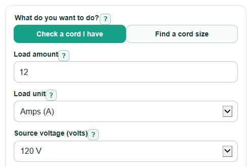
- Choose What do you want to do?: check a cord you already have, or find the smallest common Cord wire size that passes.
- Enter the Load amount, choose Load unit, pick Source voltage, and enter the one-way Cord length in feet.
- If you are checking a cord, choose its Cord wire size; remember that a smaller AWG number means a thicker cord.
- Open Advanced options if needed, then set Largest voltage drop to allow, Will it run for 3 hours or more?, and Smallest plug, outlet, or printed cord rating.
- After you calculate, sanity-check the Answer, Most current this setup should carry, and What limits the setup; if the load is above the limit, shorten the cord, use a thicker cord, or reduce the load.
Definitions
AWG: American Wire Gauge. It is the wire-size scale used for cords. A smaller AWG number means a thicker wire.
Ampacity: The current a cord conductor can carry without getting too hot under the planning conditions used by the calculator.
Voltage drop: Voltage lost as current moves through the cord resistance. Long cords, thin cords, and higher current increase it.
Load current: The current used by the device. If you enter watts, the calculator divides watts by Source voltage to estimate amps.
Continuous load: A load expected to run for 3 hours or more. The calculator uses 80% of the base cord ampacity for this case.
Round-trip resistance: The resistance of both conductors in the cord path, because current travels to the device and back.
Common mistakes and quick fixes
Mistake: Entering a watt value in Load amount while Load unit is set to Amps (A).
Fix: Match Load unit to the unit on the device label, or change Load amount to the correct amp value.
Mistake: Doubling Cord length because electricity travels out and back.
Fix: Enter only the one-way Cord length from the outlet to the device; the calculation doubles it internally.
Mistake: Picking a larger AWG number in Cord wire size because it looks stronger.
Fix: Use the actual Cord wire size printed on the cord; with AWG, 12 AWG is thicker than 16 AWG.
Mistake: Leaving Smallest plug, outlet, or printed cord rating higher than the real outlet or cord label.
Fix: Use the lowest rating in the whole chain, such as 15 A if any part is rated 15 A.
Mistake: Choosing No for Will it run for 3 hours or more? when the load will run for a long time.
Fix: Choose Yes for long steady loads so Cord heat limit used is reduced.
Mistake: Treating Answer as a promise that any cord is safe in any condition.
Fix: Also read Safety note, and do not use a coiled, covered, damaged, wet-location-unrated, or permanently installed extension cord.
Limitations & Key Assumptions / Boundary Conditions
- This is a planning calculator for common copper extension-cord sizes from 18 AWG through 10 AWG. It does not cover every cord type, insulation rating, conductor material, temperature rating, or special industrial cord.
- The ampacity values are planning values. The printed rating on the actual cord, plug, outlet, breaker, and device instructions can be lower and should control.
- Voltage drop is estimated from conductor resistance. Real voltage at the device can differ because of outlet voltage, connectors, temperature, cord condition, and the device power factor.
- The Load amount should be the normal running load, not a motor startup surge. Motors and compressors can need much more current for a short time.
- A passing result does not make unsafe use safe. Do not run cords coiled, under rugs, through walls, through doors, in wet areas without proper outdoor rating, or as a replacement for permanent wiring.
- If no listed Cord wire size passes, the calculator does not design a different power system. Shorten the cord, reduce the load, use a properly rated circuit, or ask a qualified electrician.
Methodology
How the calculator uses your entries
The calculator first turns the Load amount into amps. If Load unit is Amps (A), it uses the entered value. If Load unit is Watts (W), it divides watts by Source voltage.
load_amps = load_watts / source_voltage
Next it looks up the selected Cord wire size in the built-in AWG table. The table uses copper resistance in ohms per 1000 ft and base flexible-cord ampacity for 18, 16, 14, 12, and 10 AWG.
round_trip_resistance_ohms = 2 * cord_length_ft * resistance_ohms_per_1000_ft / 1000
The factor of 2 is used because Cord length is one-way length, while the electrical path goes out to the device and back.
Voltage drop and heat
Voltage lost in the cord is current times round-trip resistance.
voltage_drop_volts = load_amps * round_trip_resistance_ohms
voltage_drop_percent = 100 * voltage_drop_volts / source_voltage
voltage_at_device_volts = source_voltage - voltage_drop_volts
The calculator also estimates heat made in the cord.
power_loss_watts = load_amps * load_amps * round_trip_resistance_ohms
Current limits
The heat limit starts with the base ampacity for the chosen AWG. If Will it run for 3 hours or more? is Yes, the calculator multiplies that ampacity by 0.8.
heat_limit_amps = base_ampacity_amps * continuous_factor
The voltage-drop limit is the current that would exactly hit the selected Largest voltage drop to allow.
drop_limit_amps = (source_voltage * max_drop_percent / 100) / round_trip_resistance_ohms
Most current this setup should carry is the smallest of the heat limit, voltage-drop limit, the equipment rating, and the separately selected breaker limit. The breaker limit is multiplied by 0.8 for a continuous load; the equipment nameplate cap is not multiplied again.
max_usable_current_amps = min(heat_limit_amps, drop_limit_amps, rating_limit_amps_if_used, breaker_limit_amps_if_used)
What limits the setup names the smallest limit. In check mode, Answer passes only when the load current is less than or equal to that smallest limit. In find mode, the calculator tests 18, 16, 14, 12, then 10 AWG and returns the first size that passes.
recommended_awg = first_awg_in_order_where(load_amps <= min(heat_limit_amps, drop_limit_amps, rating_limit_amps_if_used, breaker_limit_amps_if_used))
Mini example
For a 12 A load on a 50 ft, 12 AWG cord at 120 V, the round-trip resistance is 2 * 50 * 1.588 / 1000 = 0.1588 ohms. Voltage lost in the cord is 12 * 0.1588 = 1.9056 V, or 1.588% of 120 V. The estimated voltage at the device is 118.0944 V, and heat in the cord is 12 * 12 * 0.1588 = 22.8672 W. With a 15 A plug or outlet limit, the most current this setup should carry is 15 A, so a 12 A load passes the calculated checks.
Sources
- Kansas Fire Marshal: extension cords - KS
- University of Kansas EHS - Electrical Extension Cords and Power Strips (gauge, warmth, loading guidance) - KU
- Extension Cord Size Guide: Wire Gauge, Amps & Length - Allstar Electrical - Allstarelectrical
- What Gauge Extension Cord Do I Need? Extension Cord Safety Guide - KMC
For motors and other non-unity power-factor loads, use nameplate input amps instead of estimating amps from watts. Standard-breaker reference: Schneider Electric continuous-load guidance.