
Find a planning wire size or check a chosen wire against load, terminal rating, heat, and conductor-count derating.
Table of contents
How to use our Wire Ampacity Calculator
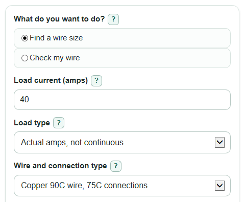
- Choose What do you want to do?: Find a wire size for a new design, or Check my wire if you already picked a Wire size.
- Enter Load current (amps), then choose Load type. Pick continuous load only when the load is expected to run for 3 hours or more.
- Choose Wire and connection type. Match the conductor material, insulation temperature rating, and the lowest terminal rating on the equipment.
- Open Advanced options if the wire is in a hot area or shares a raceway or cable with several current-carrying conductors. Enter Ambient air temperature (F) and Current-carrying conductors in the raceway or cable.
- Click Calculate and sanity-check the result: Usable ampacity should be at least Required ampacity, and What limited the result should make sense for your setup.
Definitions
Ampacity: The maximum current a conductor is allowed to carry under the table conditions and any required corrections.
Required ampacity: The amps the wire must be able to carry after the selected Load type is applied.
Usable ampacity: The final ampacity used for the pass/fail check, using the lower of the derated insulation ampacity and the connection-limited ampacity.
AWG: American Wire Gauge, a size system where a smaller number usually means a larger wire.
kcmil: A large-conductor size unit equal to 1,000 circular mils.
Continuous load: A load expected to run for 3 hours or more; this calculator multiplies the entered amps by 1.25 when that Load type is selected.
Ambient air temperature: The air temperature around the wire, not necessarily the room temperature.
Current-carrying conductors: Conductors that normally carry current in the raceway or cable. Equipment grounding conductors are not counted here.
Connection-limited ampacity: The ampacity limit from the terminal or equipment connection temperature rating.
Common mistakes and quick fixes
Mistake: Entering breaker size in Load current (amps) instead of the actual load amps.
Fix: Use the equipment nameplate, plan value, or load calculation for Load current (amps).
Mistake: Leaving Load type on actual amps for a load that runs for 3 hours or more.
Fix: Change Load type to Continuous load, use 125% when the continuous-load rule applies.
Mistake: Choosing Wire and connection type by the wire insulation only and ignoring the equipment terminals.
Fix: Pick the option that includes the lowest terminal rating, such as 60C connections or 75C connections.
Mistake: Using room temperature for Ambient air temperature (F) when the wire is in an attic, conduit, or equipment space.
Fix: Enter the hottest expected air around the wire in Ambient air temperature (F).
Mistake: Counting every wire for Current-carrying conductors in the raceway or cable, including equipment grounding conductors.
Fix: Count only conductors that normally carry current, and check neutral counting rules for the circuit type.
Mistake: Treating Small wire breaker note as the full breaker-size answer.
Fix: Use Small wire breaker note as a reminder, then verify overcurrent protection with the current code and a qualified electrician or inspector.
Limitations & Key Assumptions / Boundary Conditions
- This is a planning calculator. Final wiring must follow the current NEC edition adopted in your area, local amendments, equipment instructions, and inspection requirements.
- The lookup is NEC-style table math for common copper and aluminum conductors from 14 AWG through 2000 kcmil. It is not a heat-transfer model.
- The calculator does not include voltage drop, conduit fill, rooftop temperature adders, service conductor rules, cable tray rules, flexible cord tables, parallel conductor rules, or local code changes.
- Breaker or fuse sizing is not fully calculated. The Small wire breaker note is only a reminder for common small conductors.
- Ambient air temperature (F) uses a table range. Temperatures outside the loaded correction table are treated as unsupported instead of being guessed.
- Current-carrying conductor count can depend on neutral behavior and circuit type. If you are not sure what to count, check the code, plans, or a qualified electrician.
- Some equipment has special terminal ratings, conductor material limits, or manufacturer instructions that are stricter than the general table method.
Methodology
Calculation steps
The calculator uses an NEC-style ampacity table lookup by conductor material, Wire size, and 60C, 75C, or 90C temperature column. Table 310.16 style ampacity depends on factors such as conductor material and size [2].
required_ampacity = load_amps * load_multiplier
The load multiplier is 1 for Actual amps, not continuous. It is 1.25 for Continuous load, use 125%.
ambient_c = (ambient_f - 32) * 5 / 9
The ambient temperature in Celsius is used to choose the temperature correction factor for the selected wire insulation rating.
derated_insulation_ampacity = base_ampacity_at_wire_rating * ambient_factor * conductor_count_factor
The conductor-count factor is chosen from the step table:
1 to 3 conductors = 1.00, 4 to 6 = 0.80, 7 to 9 = 0.70, 10 to 20 = 0.50, 21 to 30 = 0.45, 31 to 40 = 0.40, and 41 or more = 0.35.
terminal_limited_ampacity = base_ampacity_at_connection_rating
This step prevents a high-temperature insulation value from being used above the rating of the terminals or equipment lugs.
usable_ampacity = min(derated_insulation_ampacity, terminal_limited_ampacity)
ampacity_margin = usable_ampacity - required_ampacity
In Find a wire size mode, the calculator tests the listed sizes from smallest physical size to largest and returns the first size where usable ampacity is at least required ampacity. In Check my wire mode, it tests only the chosen Wire size and reports pass or fail.
Worked example
For a 40 amp actual load using Copper 90C wire, 75C connections at 86F with 3 current-carrying conductors, required ampacity is 40 * 1 = 40 A. For 8 AWG copper, the 90C base value is 55 A, the ambient factor is 1.00, and the conductor-count factor is 1.00, so derated insulation ampacity is 55 A. The 75C connection-limited ampacity is 50 A. Usable ampacity is the lower value, 50 A, so the margin is 50 - 40 = 10 A and 8 AWG is the smallest listed size that passes for this setup.