
Use this buck calculator to size an ideal step-down converter and check whether your chosen inductor stays in continuous current.
Advanced options
Table of contents
How to use our Buck Calculator
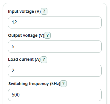
- Enter Input voltage, Output voltage, Load current, Switching frequency, and Inductor you plan to use.
- Open Advanced options if you want to change Target current ripple, Allowed output ripple, Output capacitor ESR, Allowed input ripple, Expected efficiency, or Number display.
- Click Calculate and read Suggested inductor for your ripple target first, then compare it with Current ripple with your inductor and Smallest inductor for continuous current at this load.
- Sanity-check the answer: Duty cycle should be less than 100%, Inductor current low point should stay above 0 A for CCM, and Peak inductor current should be below your part limits with margin.
Definitions
Buck converter: A switching circuit that makes a lower DC output voltage from a higher DC input voltage.
Duty cycle: The percent of each switching cycle that the high-side switch is on.
Current ripple: The small up-and-down change in inductor current during one switching cycle, shown as peak-to-peak current.
CCM: Continuous conduction mode, meaning the inductor current never falls to zero during normal switching.
Peak inductor current: The highest ideal current through the inductor during a cycle.
Inductor current low point: The lowest ideal current through the inductor during a cycle; a negative value means the CCM math has crossed its boundary.
ESR: Equivalent series resistance, a small internal resistance in a capacitor that creates extra ripple voltage.
RMS current: A heating-related current value used to compare against capacitor ripple-current ratings.
Common mistakes and quick fixes
Mistake: Entering an Input voltage that is equal to or lower than Output voltage.
Fix: Use a higher Input voltage because a buck converter steps voltage down.
Mistake: Typing Switching frequency in Hz when the field expects kHz.
Fix: Convert first, so 500000 Hz is entered as 500 in Switching frequency.
Mistake: Leaving Target current ripple blank or using 0%.
Fix: Enter a positive Target current ripple so Suggested inductor for your ripple target can be calculated.
Mistake: Treating Inductor current low point as a real negative current in a normal buck converter.
Fix: Read a negative Inductor current low point as a warning that the converter would leave continuous current at that load.
Mistake: Setting Output capacitor ESR so high that Ripple caused by output capacitor ESR uses the whole Allowed output ripple budget.
Fix: Lower Output capacitor ESR or raise Allowed output ripple before trusting Minimum output capacitor for the ripple goal.
Mistake: Using Estimated average input current as the input capacitor ripple rating.
Fix: Use Input capacitor RMS current for capacitor heating stress, and use Estimated average input current for the source current estimate.
Limitations & Key Assumptions / Boundary Conditions
- The formulas use an ideal buck model. They ignore switch voltage drop, diode drop or synchronous FET losses, inductor resistance, switching loss, control-loop behavior, board layout, and temperature.
- Input voltage must be higher than output voltage. If it is not, the buck-converter equations do not apply.
- The CCM results are most useful when Inductor current low point is above 0 A. If it is negative, the real converter would hit zero current and discontinuous-current behavior changes the exact ripple and duty cycle.
- Minimum output capacitor for the ripple goal is a ripple estimate only. Real capacitors lose capacitance with DC bias, temperature, tolerance, and aging, so datasheet derating matters.
- Minimum input capacitor for the input ripple goal ignores source impedance and PCB trace inductance. Follow the regulator datasheet layout rules and place input capacitors close to the pins.
- Peak inductor current and Input capacitor RMS current are ideal stress checks. Choose real parts with voltage, current, saturation, temperature, and safety margin above the calculated values.
- Expected efficiency is used only for Estimated average input current. It does not change the ideal duty cycle, ripple, or capacitor sizing equations.
Methodology
Core buck equations
The calculator treats the circuit as an ideal continuous-mode buck converter, so losses are ignored when finding duty cycle and ripple. Ideal buck design equations commonly use this type of simplified model [2].
D = Vout / Vin
duty_cycle_pct = 100 * D
For the inductor you entered, inductance is converted from uH to H and switching frequency is converted from kHz to Hz.
delta_I_L = Vout * (Vin - Vout) / (Vin * L * fs)
actual_ripple_pct = 100 * delta_I_L / Iout
The suggested inductor uses your Target current ripple as a fraction of Load current.
L_target = Vout * (Vin - Vout) / (Vin * fs * (Iout * target_ripple_decimal))
suggested_inductor_uh = L_target * 1000000
Current checks
Peak and low-point current are found by adding or subtracting half of the ripple from the load current.
I_peak = Iout + delta_I_L / 2
I_valley = Iout - delta_I_L / 2
L_crit = Vout * (Vin - Vout) / (2 * Vin * fs * Iout)
If I_valley is below 0 A, the calculator keeps the negative value because the sign is the warning: the ideal continuous-current model is no longer a good match at that load.
Capacitor estimates
Output ripple is split into ESR ripple and the remaining ripple that the ideal capacitance must handle.
V_esr = delta_I_L * ESR
C_out_min = delta_I_L / (8 * fs * (Vout_ripple_goal - V_esr))
If Vout_ripple_goal is less than or equal to V_esr, the calculator shows N/A for Minimum output capacitor for the ripple goal because capacitance alone cannot fix an ESR ripple budget that is already used up.
Input capacitor stress is estimated from the ideal pulsed input current shape.
I_cin_rms = Iout * sqrt(D * (1 - D))
C_in_min = Iout * D * (1 - D) / (fs * Vin_ripple_goal)
The average input current estimate uses the entered efficiency.
Iin_avg = (Vout * Iout) / (Vin * efficiency_decimal)
Mini example
With Input voltage = 12 V, Output voltage = 5 V, Load current = 2 A, Switching frequency = 500 kHz, Inductor you plan to use = 10 uH, and Target current ripple = 30%, the duty cycle is 5 / 12 = 0.4167, or 41.67%.
The entered 10 uH inductor gives delta_I_L = 0.5833 A peak-to-peak, so the peak current is 2.2917 A and the low point is 1.7083 A. The target-ripple inductor is 9.7222 uH, so a nearby standard value near 10 uH matches the target closely.