
Use this boost calculator to estimate duty cycle, inductor size, capacitor size, and current stress for a DC step-up supply.
Table of contents
How to use our Boost Calculator
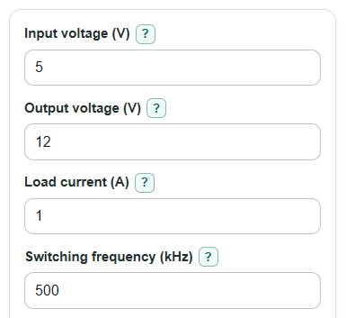
- Enter the lowest expected Input voltage (V), because a weak battery or long wire drop usually creates the hardest design case.
- Enter the Output voltage (V) and Load current (A) your circuit must supply; Output voltage must be higher than Input voltage for this boost-only model.
- Enter the Switching frequency (kHz) and Inductor current ripple target (%); 20% to 40% is a common first-pass range, but your controller data sheet may suggest a different target.
- Open Advanced options if you want the Expected efficiency (%), Diode voltage drop (V), Switch voltage drop (V), or Output ripple target (mV peak-to-peak) to reflect your real parts.
- After calculating, sanity-check the Duty cycle, Peak inductor current, Lowest inductor current, and Design notes before picking parts; high duty cycle or near-zero lowest current means the simple model needs extra caution.
Definitions
Boost converter: A DC-DC power circuit that raises a lower DC Input voltage to a higher Output voltage.
Duty cycle: The percent of each switching cycle when the switch is on. A higher Duty cycle usually means more current stress.
Switching frequency: How many switching cycles happen each second. The calculator uses kHz, where 1 kHz equals 1000 cycles per second.
Inductor current ripple: The small up-and-down change in inductor current during each switching cycle, shown as peak-to-peak current.
Inductor: A part that stores energy in a magnetic field while current flows through it [1]. In a boost converter, it is the main energy-transfer part.
Output ripple target: The allowed up-and-down change in Output voltage, entered in mV peak-to-peak.
RMS current: A heating-related current value. For the same wire resistance, higher RMS current means more winding heat.
ESR: Equivalent series resistance, the small real resistance inside a capacitor. ESR can add output ripple that the ideal capacitor formula does not include.
Common mistakes and quick fixes
Mistake: Using a typical battery value for Input voltage instead of the lowest voltage the converter must survive.
Fix: Put the worst-case low Input voltage in the box so Duty cycle and Peak inductor current are not underestimated.
Mistake: Entering Output voltage that is equal to or lower than Input voltage.
Fix: Use this page only when Output voltage is higher than Input voltage; a lower output needs a buck or buck-boost design instead.
Mistake: Leaving Inductor current ripple target blank or using 0%.
Fix: Enter a positive Inductor current ripple target, because Minimum inductor value divides by the ripple current.
Mistake: Setting Expected efficiency to 100% when you are checking real current stress.
Fix: Use a realistic Expected efficiency so Average input current and Peak inductor current include loss margin.
Mistake: Treating Minimum output capacitor as the final capacitor choice.
Fix: Use Minimum output capacitor as an ideal starting point, then increase it for tolerance, DC bias, ESR, layout, and load transients.
Mistake: Ignoring Lowest inductor current when it is near zero or negative.
Fix: If Lowest inductor current is near zero or below zero, treat the continuous-current result as weak and check the controller data sheet or redesign with a different ripple target.
Limitations & Key Assumptions / Boundary Conditions
- This calculator is for a basic boost converter where Output voltage is higher than Input voltage.
- The equations use a continuous-current model with triangular inductor current ripple. If Lowest inductor current is near zero or negative, the model may not match the real circuit.
- Minimum output capacitor is an ideal capacitive-ripple estimate. It does not include capacitor ESR, tolerance, DC bias loss, aging, layout inductance, or load-step response.
- Expected efficiency is a user estimate. Wrong efficiency can make Average input current, Peak inductor current, and inductor sizing look safer than they are.
- Diode voltage drop and Switch voltage drop are treated as fixed values, but real drops change with current, temperature, and device choice.
- Duty cycle values above about 85% are flagged because many controllers have maximum duty-cycle limits, slow transient response, or high current stress near that range.
- The results do not choose a real controller, diode, MOSFET, inductor saturation rating, capacitor voltage rating, compensation network, or PCB layout.
Methodology
Calculation flow
The calculator first converts Switching frequency from kHz to Hz, Expected efficiency from percent to a decimal, Inductor current ripple target from percent to a decimal, and Output ripple target from mV to V.
fsw_Hz = Switching frequency * 1000
eta = Expected efficiency / 100
Vripple_V = Output ripple target / 1000
It then estimates the adjusted boost duty cycle. With Diode voltage drop and Switch voltage drop set to 0, this becomes the ideal boost result.
D = (Vout + Vd - Vin) / (Vout + Vd - Vsw)
Average input current is estimated from power balance, so lower Expected efficiency increases the input current estimate.
Iin_avg = (Vout * Iout) / (Vin * eta)
The requested ripple percent sets the inductor current change. The Minimum inductor value uses the inductor on-time voltage and the switching period.
Delta_IL = Iin_avg * (Inductor current ripple target / 100)
L_H = (Vin - Vsw) * D / (fsw_Hz * Delta_IL)
Minimum inductor value in uH = L_H * 1000000
Current stress is calculated from the average input current and triangular ripple shape.
Peak inductor current = Iin_avg + Delta_IL / 2
Lowest inductor current = Iin_avg - Delta_IL / 2
Inductor RMS current = sqrt(Iin_avg^2 + Delta_IL^2 / 12)
The output capacitor estimate uses the load current that the capacitor must supply during the switch on-time.
Cout_F = Iout * D / (fsw_Hz * Vripple_V)
Minimum output capacitor in uF = Cout_F * 1000000
Worked mini-example
For Input voltage = 5 V, Output voltage = 12 V, Load current = 1 A, Switching frequency = 500 kHz, Inductor current ripple target = 30%, Expected efficiency = 90%, Diode voltage drop = 0.4 V, Switch voltage drop = 0.1 V, and Output ripple target = 50 mV peak-to-peak, the adjusted Duty cycle is 60.16%.
The Average input current is 2.667 A, the Inductor current ripple is 0.800 A peak-to-peak, the Minimum inductor value is 7.37 uH, and the Peak inductor current is 3.07 A.
The same example gives Lowest inductor current = 2.27 A, Inductor RMS current = 2.68 A, and Minimum output capacitor = 24.07 uF before real-part corrections such as ESR and tolerance.