
Enter your pipe and slurry data to check carrying velocity, pressure drop, total pump head, and preliminary pump power at one flow.
Table of contents
How to use our Slurry Pipeline Velocity, Pressure Drop and Pump Power Calculator
- Enter the expected Slurry flow rate and the actual measured or specified Actual pipe inside diameter, not the nominal pipe size.
- Enter the full route distance as Developed pipe length and enter Net elevation gain as discharge elevation minus suction elevation. A downhill route has a negative value.
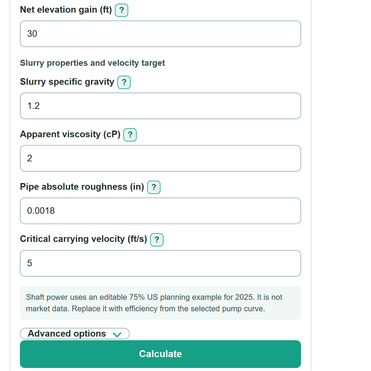
- Enter the measured slurry properties: Slurry specific gravity, Apparent viscosity, and the pipe's Pipe absolute roughness.
- Enter the slurry-specific Critical carrying velocity. In Advanced options, add fitting K, a project velocity margin, and pump efficiency from the proposed pump curve if available.
- Click Calculate. Check that actual slurry velocity is at or above minimum design velocity, then compare total dynamic head and estimated pump shaft power with the pump curve and equipment limits.
Definitions
Actual pipe inside diameter: The open diameter that slurry flows through. It can differ from nominal pipe size because of wall thickness, lining, wear, or deposits.
Critical carrying velocity: A slurry-specific minimum velocity used to reduce the risk of solids settling. This calculator uses the value you enter rather than creating one from incomplete slurry data.
Velocity design margin: An optional percentage added above critical carrying velocity to create the minimum design velocity target.
Specific gravity: Slurry density divided by water density. A value of 1.2 means the modeled slurry is 1.2 times as dense as water.
Apparent viscosity: A single viscosity value used to approximate how the slurry resists flow at a relevant test condition. It is entered in centipoise (cP).
Total fitting loss K: The combined dimensionless loss coefficient for valves, elbows, tees, reducers, entrances, exits, and other minor-loss items.
Total dynamic head: Straight-pipe friction head plus fitting head plus signed net elevation gain, reported in feet of slurry.
Hydraulic power: Power transferred to the slurry. Estimated pump shaft power is hydraulic power divided by pump efficiency.
Common mistakes and quick fixes
Mistake: Entering nominal pipe size as Actual pipe inside diameter.
Fix: Use the hydraulic inside diameter from the pipe schedule, DR, lining record, or field measurement.
Mistake: Using straight-line site distance for Developed pipe length.
Fix: Enter the full developed route length from an isometric, route survey, or takeoff.
Mistake: Leaving out elevation because Pipe and fitting pressure drop already looks like a pressure requirement.
Fix: Enter Net elevation gain separately. It is added to friction and fitting head in Total dynamic head.
Mistake: Treating Critical carrying velocity as a universal slurry value.
Fix: Use a value from testwork, operating history, a project specification, or a validated slurry method for the material being pumped.
Mistake: Reading Hydraulic power delivered to the slurry as motor power.
Fix: Use Estimated pump shaft power for the preliminary pump duty, then separately review motor and drive losses.
Mistake: Entering a negative Total fitting loss K to offset pipe losses.
Fix: Enter Total fitting loss K as zero or a positive summed loss coefficient. A downhill effect belongs in Net elevation gain.
Limitations & Key Assumptions / Boundary Conditions
- This is a steady-state screening calculation for one operating flow. It does not calculate startup, shutdown, surge, water hammer, or transient pressure.
- The slurry is modeled as a homogeneous fluid with one bulk specific gravity and one apparent viscosity. Settling behavior, particle size distribution, yield stress, concentration changes, and non-Newtonian rheology can change real pressure loss.
- The entered Critical carrying velocity controls the velocity check. Its accuracy depends on slurry testwork, operating history, or a validated project method.
- Pipe roughness, actual inside diameter, and Total fitting loss K can change with lining, corrosion, wear, deposits, valves, and final routing.
- Estimated pump shaft power uses the entered Pump efficiency. It excludes motor efficiency, drive losses, pump-curve limits, NPSH review, wear allowance, and equipment pressure ratings.
- A negative Total dynamic head or Required pump pressure increase means modeled downhill static head exceeds modeled losses. It does not mean a negative motor can be selected; pressure control and transient review may still be needed.
Methodology
Calculation method
The calculator converts flow from gpm to cubic feet per second and converts actual inside diameter from inches to feet. It finds internal pipe area, then divides flow by area to calculate average slurry velocity.
A = πD^2 / 4
v = Q / A
Minimum design velocity is the entered critical carrying velocity increased by the optional velocity design margin. The minimum required flow is the flow that reaches that velocity in the entered actual inside diameter.
v_design = v_critical x (1 + margin / 100)
Q_min = v_design x A x 60 / 0.133680556
The model calculates Reynolds number from slurry density, apparent viscosity, velocity, and pipe diameter. It uses 64 divided by Reynolds number in the laminar range, the Swamee-Jain explicit estimate in the turbulent range, and linear interpolation from Reynolds number 2,300 to 4,000.
h_f = f x (L / D) x v^2 / (2 x 32.174)
Fitting head is total fitting loss K times velocity head. Total dynamic head adds straight-pipe friction head, fitting head, and signed net elevation gain. Pressure uses slurry specific gravity and 62.4 lbf/ft3 as the water reference density.
TDH = h_f + h_K + elevation_gain
pump_pressure = SG x 62.4 x TDH / 144
Hydraulic power uses flow times pump pressure divided by 1,714. Shaft power divides hydraulic power by the entered pump efficiency as a decimal.
hydraulic_hp = gpm x psi / 1714
shaft_hp = hydraulic_hp / (efficiency / 100)
Worked check
With an 8 in actual inside diameter, a critical carrying velocity of 5 ft/s, and a 10 percent velocity design margin, the minimum design velocity is 5.5 ft/s. The corresponding minimum flow is about 861.69 gpm. At 1,000 gpm, actual velocity is about 6.38 ft/s, which is above that target.
Model scope
Negative elevation gain is retained rather than forced to zero, so a downhill route can produce negative total dynamic head. Zero flow produces zero velocity-dependent losses and zero hydraulic power, while any entered static lift remains part of total dynamic head.