
Calculate estimated parabolic dish gain, 3 dB beamwidth, and wavelength for one frequency or both ends of a frequency range.
Table of contents
How to use our Parabolic Dish Antenna Gain and Beamwidth Calculator
- Choose One frequency for one channel or Frequency range for the low and high edges listed on an antenna specification.
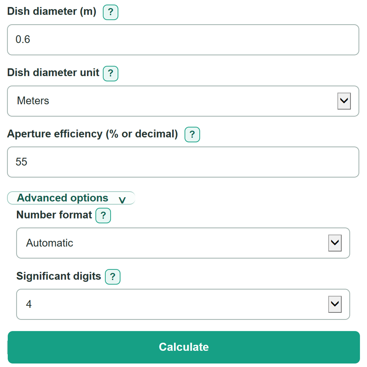
- Enter Dish diameter and choose the matching Dish diameter unit from the drawing, product specification, or measurement.
- Enter the active frequency or range, choose the matching Frequency unit, and enter Aperture efficiency (% or decimal). You can enter 55, 55%, or 0.55 for 55 percent.
- Click Calculate. Check that the displayed wavelength makes sense for the frequency unit you entered; 5 GHz should produce a wavelength close to 0.06 m, not 60 m.
Definitions
Aperture efficiency: The fraction of a dish's physical collecting area that effectively contributes to gain. Enter 55, 55%, or 0.55 for 55 percent.
dBi: Decibels relative to an ideal isotropic antenna, which radiates equally in every direction. Higher dBi means more directional gain. [1]
3 dB beamwidth: The full angle between the two directions where radiated power has dropped to half of its peak value. A smaller number means tighter pointing.
Wavelength: The distance a radio wave travels in one cycle. It equals the speed of light divided by frequency. [2]
Frequency range: A lower and upper operating frequency. The calculator reports separate estimates at both endpoints.
Common mistakes and quick fixes
Mistake: Entering 5000 while Frequency unit is set to GHz, when the radio shows 5000 MHz.
Fix: Choose MHz, or enter 5 and keep GHz selected.
Mistake: Typing an inch or millimeter measurement into Dish diameter while Dish diameter unit is set to Meters.
Fix: Select the unit shown on the specification before entering the diameter.
Mistake: Treating Aperture efficiency (% or decimal) as cable loss or total system efficiency.
Fix: Enter reflector aperture efficiency only. Keep cable, connector, feed, and pointing losses separate from this estimate.
Mistake: Entering the upper band edge as Low frequency and the lower edge as High frequency.
Fix: Put the smaller number in Low frequency and the larger number in High frequency.
Mistake: Expecting Estimated 3 dB beamwidth at selected or low frequency to exactly match a manufacturer's horizontal or vertical value.
Fix: Use the calculated value for planning and compare it cautiously with the manufacturer's measured pattern data.
Limitations & Key Assumptions / Boundary Conditions
- Gain and beamwidth are planning estimates for a circular parabolic aperture, not guaranteed manufacturer ratings or measured radiation patterns.
- The calculation uses one dish diameter and one aperture-efficiency value across the selected frequency or range. Actual efficiency can change with frequency.
- The 3 dB beamwidth estimate uses a factor of 70 and produces one angle. A real antenna may have different horizontal and vertical beamwidths.
- Feed illumination, subreflector or feed blockage, reflector surface error, radomes, polarization, pointing error, and installation effects are not modeled.
- Cable, connector, and receiver losses are not included. They affect received or transmitted system performance, not the dish-only gain estimate shown here.
- The speed of light is used for free-space wavelength. Propagation in a cable or other material has a different wave speed.
Methodology
Calculation method
The calculator first converts Dish diameter to meters and the active frequency to hertz. In the formulas below, D is dish diameter in meters, f is frequency in hertz, η is aperture efficiency as a fraction, and λ is wavelength in meters.
λ (wavelength in m) = 299792458 / f (frequency in Hz)
The speed of light in vacuum is exactly 299,792,458 m/s. [2]
G (linear gain) = η (aperture efficiency) x (π x D / λ)^2
Gain (dBi) = 10 x log10(G)
This is the standard ideal parabolic-aperture gain relationship adjusted by aperture efficiency. [1]
3 dB beamwidth (degrees) = 70 x λ / D
The 70-degree multiplier is a practical circular-dish planning approximation for the full half-power beamwidth. A shorter wavelength or larger dish raises estimated gain and narrows the beam.
Frequency range mode
With Frequency range selected, the calculator runs the wavelength, gain, and beamwidth equations once at Low frequency and once at High frequency. It does not use the hidden one-frequency field.
Worked example
For a 0.6 m dish at 5 GHz with 55 percent aperture efficiency, wavelength is about 0.05996 m, estimated gain is about 27.35 dBi, and estimated 3 dB beamwidth is about 7.00 degrees. Changing only frequency to 6 GHz makes the wavelength shorter, increases the gain estimate, and narrows the beamwidth estimate.
Assumptions and limits
The model assumes a correctly shaped circular reflector and does not calculate feed losses, cable losses, surface errors, or separate horizontal and vertical patterns. Use manufacturer test data and a full link budget when an installation decision depends on small differences.