
Estimate centrifugal-pump flow, total head, and shaft power after changing speed or trimming an impeller.
Known pump duty point
Advanced options
Calculation details
Table of contents
How to use our Pump Affinity Laws Calculator
- Choose What are you changing? and enter one known pump duty point using Reference flow, Reference total head, and Reference pump shaft power.
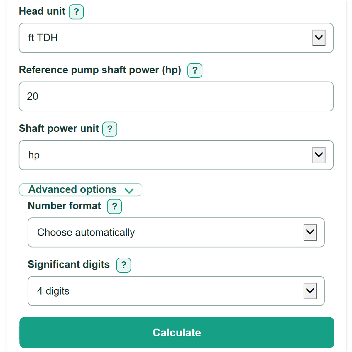
- Choose the matching Flow unit, Head unit, and Shaft power unit from the pump curve or commissioning record.
- For a speed change, choose the Speed entry basis and enter both Reference speed and Proposed speed. For a trim, choose the Impeller diameter unit and enter the original and trimmed diameters.
- Click Calculate, then compare the estimated flow, head, and shaft power with the manufacturer pump curve and your system curve before changing equipment.
- Sanity-check the direction: reducing speed or trimming the impeller should produce lower estimated flow, head, and pump shaft power.
Definitions
Reference duty point: A known pump operating point containing flow, total head, and pump shaft power measured or listed together.
Total dynamic head (TDH): The total head the pump must produce, commonly shown as feet of head or meters of head on a pump curve.
Pump shaft power: Power delivered to the pump shaft, often called brake horsepower. It is different from motor nameplate power and electrical power drawn from the utility.
Speed or diameter ratio: Proposed speed divided by reference speed, or trimmed impeller diameter divided by original impeller diameter.
Impeller trim: Reducing an impeller's outside diameter to change pump performance. The allowed trim range depends on the specific pump and manufacturer curve.
Affinity laws: Ratio-based relationships used as a first-pass estimate of how centrifugal-pump flow, head, and shaft power change with speed or impeller diameter. [2]
Common mistakes and quick fixes
Mistake: Using values from different operating points for Reference flow, Reference total head, and Reference pump shaft power.
Fix: Copy all three values from the same point on one pump curve or from the same measured duty point.
Mistake: Entering a gauge pressure in Reference total head.
Fix: Enter total dynamic head in the selected Head unit. Do not treat psi as feet of head.
Mistake: Mixing RPM and Hz between Reference speed and Proposed speed.
Fix: Set Speed entry basis first, then enter both speeds using that same basis.
Mistake: Entering motor nameplate rating as Reference pump shaft power.
Fix: Use brake or shaft power at the known duty point from a pump curve or selection report. Nameplate motor power can be higher.
Mistake: Making Trimmed impeller diameter larger than Original impeller diameter.
Fix: Enter a trimmed diameter no larger than the original diameter, then verify the permitted trim with the manufacturer.
Mistake: Treating Estimated new flow as the guaranteed operating flow.
Fix: Use Pump curve check as a reminder to compare the estimate with the manufacturer curve and the actual system curve.
Limitations & Key Assumptions / Boundary Conditions
- The calculation assumes a centrifugal pump and starts from one valid reference duty point with flow, total head, and shaft power from the same condition.
- It estimates scaled pump performance. The actual operating point can differ because of the system curve, static head, throttling, piping changes, or changing fluid conditions.
- Estimated pump shaft power is not electrical input power, energy use, or utility-bill savings. Motor efficiency, VFD efficiency, demand charges, and operating hours are not included.
- Verify NPSH, minimum-flow limits, motor and drive limits, vibration, and other equipment limits before making a speed change.
- Impeller-trim results are first-pass estimates only. Confirm the permitted trim range and revised manufacturer curve for the exact pump model and impeller.
- Unit selectors convert compatible measurements, but a pressure reading in psi requires fluid-specific conversion to head before it can be used as total head.
Methodology
Calculation method
The calculator uses one ratio based on the selected change. In speed mode, both speed entries must use the same basis. In impeller-trim mode, both diameter entries use the selected diameter unit. The affinity-law relationships scale flow by the ratio, total head by its square, and pump shaft power by its cube. [2]
ratio = proposed speed / reference speed
ratio = trimmed impeller diameter / original impeller diameter
estimated new flow = reference flow * ratio
estimated new total head = reference total head * ratio^2
estimated new pump shaft power = reference pump shaft power * ratio^3
percent change = (ratio^power - 1) * 100
Worked example
For a speed reduction from 1,800 RPM to 1,440 RPM, the ratio is 1,440 / 1,800 = 0.8. Starting with 1,000 GPM, 100 ft TDH, and 20 hp, the estimates are 800 GPM, 64 ft TDH, and 10.24 hp. Flow changes by -20%, head by -36%, and shaft power by -48.8%.
Units and rounding
Changing a unit selector converts the value already entered rather than treating the same number as a different unit. The calculator uses standard conversions for US gallons, feet, inches, mechanical horsepower, and metric units. [1] Number format and Significant digits change only how results are displayed.
Assumptions and limits
The equations provide a first-pass pump estimate, not a replacement for the manufacturer curve or a system-curve analysis. They do not model changing efficiency, NPSH, static head, motor limits, VFD behavior, or the specific effects of an impeller trim on a particular pump.