
Check a radio path over one obstacle and find the antenna height increase needed to meet your selected Fresnel clearance target.
Site 1
Site 2
Obstacle
Planning defaults: K-factor 1.33 from a 1979 NTIA reference and 60% Fresnel clearance. Replace them with your project criteria, local manual, or provider standard.
Advanced options
This amount applies separately to each site.
Calculation details
Table of contents
How to use our Fresnel Zone Clearance and Antenna Height Calculator
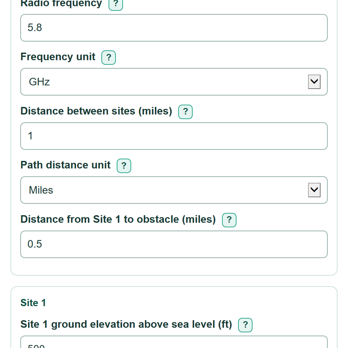
- Enter the Radio frequency and choose its printed unit under Frequency unit.
- Enter the full Distance between sites, then enter Distance from Site 1 to obstacle using the same Path distance unit.
- Choose Height and elevation unit, then enter each site's ground elevation above sea level and antenna center height above ground.
- Enter the ground elevation and height of the obstacle. Use 0 for Obstacle height above local ground when the obstacle is bare terrain.
- Click Calculate, then compare Available clearance above the obstacle with Required Fresnel clearance at the obstacle. Confirm that the derived distance to Site 2 matches your map before using an antenna-height recommendation.
Definitions
Fresnel zone: An area around the direct radio path where objects can weaken or disturb the signal.
First Fresnel-zone radius: The distance from the path centerline to the edge of the first Fresnel zone at the obstacle location.
MSL: Mean sea level. Ground elevation above sea level, used as a shared vertical reference for both sites and the obstacle.
AGL: Above ground level. The height of an antenna, tree, or building above its local ground.
K-factor: A unitless effective-Earth-radius setting used to estimate how atmospheric refraction changes the Earth-curvature correction.
Available clearance: The curvature-adjusted height of the radio path above the obstacle top before applying the selected Fresnel target.
Clearance margin: Available clearance minus required Fresnel clearance. A positive value meets the selected target; a negative value is a shortfall.
Common mistakes and quick fixes
Mistake: Entering a tower height in Site 1 ground elevation above sea level.
Fix: Enter ground elevation on the sea-level datum, then enter the tower or mast measurement separately in Site 1 antenna center height above ground.
Mistake: Using a tree-top elevation as Ground elevation at obstacle above sea level.
Fix: Enter terrain elevation there and put the tree or building amount in Obstacle height above local ground.
Mistake: Entering 5800 while Frequency unit is set to GHz.
Fix: Choose MHz for 5800 MHz, or enter 5.8 and choose GHz.
Mistake: Setting Distance from Site 1 to obstacle equal to or greater than Distance between sites.
Fix: Measure from Site 1 along the path. The obstacle must be strictly between the two sites.
Mistake: Treating a positive Available clearance above the obstacle as a full pass.
Fix: Also check Clearance margin above the selected target. A negative margin means the chosen Fresnel target is not met.
Limitations & Key Assumptions / Boundary Conditions
- This checks one entered obstacle only. It does not find hidden terrain, trees, buildings, or moving equipment elsewhere along the path.
- All ground elevations must use the same sea-level datum. Mixing map, GPS, and survey datums can change the result.
- The result uses a straight path between antenna centers plus a single effective-Earth-curvature correction. It does not model detailed terrain diffraction, clutter, reflections, rain, or link budget.
- K-factor and the required first Fresnel-zone clearance are planning choices. Use the values required by the project, owner, or radio design standard.
- Added antenna height is a geometric recommendation for the entered obstacle. Confirm structural limits, mounting location, permits, and actual antenna center height before installation.
- An obstacle very close to one endpoint can require a very large height increase at the opposite endpoint. That is a geometry effect, not necessarily a practical installation plan.
Methodology
Calculation method
The calculator converts all horizontal distances to meters and all elevations and heights to meters. It adds each antenna height above ground to its site's ground elevation, and does the same for the obstacle.
λ (wavelength in m) = c / f
The speed of light, c, is 299,792,458 meters per second. Frequency f is converted from the selected MHz or GHz unit to hertz. [1]
r1 = sqrt(λ * d1 * d2 / D)
r1 is the first Fresnel-zone radius, d1 is the distance from Site 1 to the obstacle, d2 is the derived distance from the obstacle to Site 2, and D is the full path distance. ITU-R P.526 describes Fresnel-zone geometry and the effective-Earth-radius diffraction model used for this planning estimate. [2]
bulge = d1 * d2 / (2 * K * R)
The curvature term uses K, the effective Earth radius factor, and R = 6,371,000 m as the mean Earth radius. The calculator subtracts this curvature rise from the straight line between the two antenna centerlines.
available clearance = sight-line height - obstacle-top height - bulge
required clearance = r1 * target percent / 100
clearance margin = available clearance - required clearance
A nonnegative clearance margin is Clear. A negative margin with nonnegative available clearance is Marginal because the optical line of sight is clear but the selected Fresnel target is missed. Negative available clearance is Blocked.
Added-height recommendations
The height shortfall is the negative clearance margin, floored at zero only for the added-height recommendations. A path that already meets the target needs no added height.
Site 1 increase = shortfall / (d2 / D)
Site 2 increase = shortfall / (d1 / D)
equal increase at both sites = shortfall
For example, with a 5.8 GHz path of 1 mile, an obstacle at 0.5 mile, 50-foot antenna heights at 500-foot ground elevations, and an obstacle top at 560 feet, the default 60 percent target produces about -19.10 feet of clearance margin. Raising both antenna centers by about 19.10 feet each meets that target; raising only one site needs about 38.20 feet.
Assumptions and limits
The method evaluates one interior path point and assumes the entered elevations use one consistent vertical datum. It keeps negative clearance values so blockage remains visible. It does not replace a terrain survey, path profile, link-budget calculation, or field test.