
Enter peak air demand, pressure, pipe length, and actual inside diameter to size one compressed-air pipe run and check its pressure drop.
The 10% pipe-drop limit and 20 ft/s speed target are editable US planning examples from a 2021 CAGI handbook. Replace them with your plant standard, equipment label, or project requirement.
Advanced options
This includes the selected fitting allowance, but not filters, dryers, regulators, hoses, or quick connects.
Calculation details
Planning calculation for steady, dry-air flow in one pipe path. It does not solve loops, branches, leaks, transients, or sonic choking.
Table of contents
How to use our Compressed Air Pipe Size and Pressure Drop Calculator
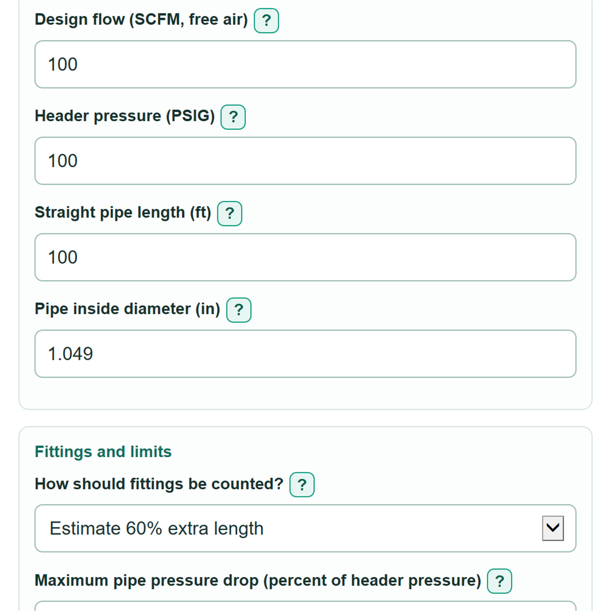
- Enter Design flow (SCFM, free air) for tools that can run at the same time, rather than average shop use.
- Enter the measured Header pressure (PSIG), Straight pipe length (ft), and actual Pipe inside diameter (in).
- Choose How should fittings be counted?. Use the 60% estimate for a quick plan, or enter documented extra length with Equivalent fitting length (ft).
- Set Maximum pipe pressure drop (percent of header pressure), then calculate. Open Advanced options if you need to change air speed, friction, local air pressure, temperature, or add a known component loss.
- Check that Entered pipe check passes both limits, and confirm that Effective pipe length used does not double-count fittings.
Definitions
SCFM (free air): Air flow stated as volume at standard free-air conditions. It is not the smaller volume occupied by that air after compression.
PSIG: Gauge pressure, measured above local atmospheric pressure. The calculator adds Local atmospheric pressure (PSIA) internally for gas calculations.
PSIA: Absolute pressure, measured from a perfect vacuum.
Actual inside diameter: The open width inside the pipe. Nominal pipe size can differ because material and wall thickness change the inside diameter.
Equivalent fitting length: Extra straight-pipe length used to approximate resistance from fittings such as elbows, tees, and valves.
Darcy friction factor: A unit-free number used in the Darcy-Weisbach pipe-friction calculation. It is not the Fanning friction factor.
Effective pipe length: Straight pipe length plus the fitting allowance selected in the calculator.
Common mistakes and quick fixes
Mistake: Entering average compressor output in Design flow (SCFM, free air).
Fix: Use the highest simultaneous SCFM demand expected on this pipe path.
Mistake: Treating nominal pipe size as Pipe inside diameter (in).
Fix: Enter the actual inside diameter from the pipe maker's dimension table or a safe measurement.
Mistake: Including elbows and valves in Straight pipe length (ft) and also adding them through Equivalent fitting length (ft).
Fix: Enter straight route length only, then use one fitting method.
Mistake: Reading Pipe-only pressure drop as the entire system loss.
Fix: Add a measured or manufacturer-supported Known downstream component loss (PSI) for losses after this pipe.
Mistake: Ignoring a failed Entered pipe check because the pressure drop looks small.
Fix: The pipe must meet both the pressure-drop limit and Maximum design air speed (ft/s).
Limitations & Key Assumptions / Boundary Conditions
- This is a planning calculation for one steady, unbranched pipe path. It does not solve loops, branches, changing tool demand, compressor cycling, or pressure waves.
- The model treats air as dry, ideal, and isothermal, meaning its temperature is held constant through the pipe. Hot compressed air, moisture, and large temperature changes can change the real pressure drop.
- The result depends directly on the entered Darcy friction factor. Pipe material, age, corrosion, deposits, fittings, and installation details can make actual resistance different.
- Use actual inside diameter, not nominal size. A pipe with the same nominal label can have a different inside diameter in another schedule or material.
- Pressure after the pipe excludes filters, dryers, regulators, hoses, quick connects, and other equipment. Estimated pressure at tool includes those only if their known loss is entered.
- The calculation stops for runs that cannot physically deliver the requested flow under the entered conditions. It does not model sonic choking.
Methodology
Calculation method
The calculator converts the entered SCFM free-air flow to mass flow using 14.7 PSIA and 68 deg F as the model's SCFM reference conditions. It converts header gauge pressure to absolute pressure by adding the entered local atmospheric pressure.
effective length = straight length, or straight length x 1.6, or straight length + equivalent fitting length
The 60% option is a simple fitting allowance. Direct equivalent length replaces that estimate rather than being added to it.
pipe area = pi x inside diameter squared / 4
outlet absolute pressure squared = inlet absolute pressure squared - friction factor x effective length x mass flow squared x air gas constant x temperature / (inside diameter x pipe area squared)
The calculator takes the positive square root of the outlet-pressure value, then subtracts outlet pressure from inlet pressure to find Pipe-only pressure drop. It divides that loss by Header pressure (PSIG) to find the displayed percentage.
pressure at tool = header pressure - pipe-only pressure drop - known downstream component loss
Minimum diameter search
The calculator tests diameters from 0.01 to 24 inches using bisection, a repeatable narrowing search. It returns the smallest inside diameter that meets both the selected pressure-drop percentage and the maximum air-speed target.
Mini-example
With 100 SCFM, 100 PSIG, 100 ft of straight pipe, and the 60% fitting estimate, the effective length is 160 ft. If pipe friction is 2.98 PSI and known downstream loss is 2 PSI, pressure after the pipe is 97.02 PSIG and estimated pressure at the tool is 95.02 PSIG.