
Enter your speaker run, wire size, load, and amplifier power to choose a copper gauge and estimate cable loss.
Advanced options
Product cable information
Number display
This uses a nominal resistive-load model. Real speaker impedance changes with frequency.
Table of contents
How to use our Speaker Cable Gauge, Voltage Drop and Power Loss Calculator
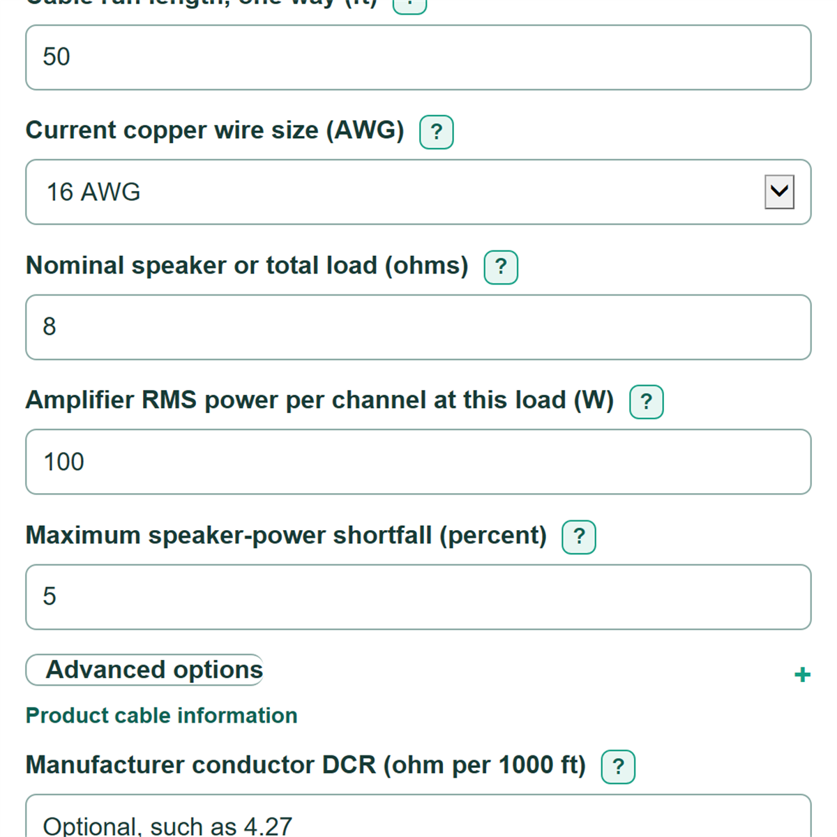
- Measure the route from the amplifier to the speaker and enter it in Cable run length, one way (ft). Do not double the distance; the calculator does that for the return conductor.
- Choose the marking printed on the cable for Current copper wire size (AWG), then enter the nominal speaker load and the amplifier RMS rating that matches that load.
- Set Maximum speaker-power shortfall (percent) to the most loss you are willing to accept, then select Calculate.
- Use Recommended copper wire size (AWG) as the smallest listed gauge that meets your target. Remember that a lower AWG number means thicker wire.
- Sanity-check Speaker-power shortfall from the selected cable against your target and confirm that the entered amplifier power is rated at the same ohm load you entered.
Definitions
AWG: American Wire Gauge, a wire-size system. Lower AWG numbers mean thicker wire with lower resistance.
Nominal load: The labeled speaker impedance, or the already-calculated total impedance of speakers sharing one run, in ohms.
DCR: DC resistance. Manufacturer conductor DCR is the resistance of one conductor, stated here in ohms per 1000 ft.
Round-trip cable resistance: The combined resistance of the outgoing and returning conductors.
Speaker-power shortfall: The modeled percent reduction in speaker power compared with an ideal cable with zero resistance.
Attenuation: Signal-level reduction stated in decibels (dB). A larger positive dB value means more cable loss.
RMS power: A steady electrical power rating used for comparing amplifier output at a stated load.
Common mistakes and quick fixes
Mistake: Entering the round-trip distance in Cable run length, one way (ft).
Fix: Enter only the amplifier-to-speaker route. Round-trip cable resistance already includes both conductors.
Mistake: Picking a larger AWG number to get thicker wire.
Fix: For Current copper wire size (AWG), a lower number is thicker: 12 AWG is thicker than 16 AWG.
Mistake: Entering amplifier watts that were rated at a different load.
Fix: Match Amplifier RMS power per channel at this load (W) to the Nominal speaker or total load (ohms) value.
Mistake: Treating Speaker-power shortfall from the selected cable as the same number as Power heating the cable loop.
Fix: Read the percent as lost speaker power versus an ideal cable, and read watts as heat dissipated in the cable.
Mistake: Adding Manufacturer conductor DCR (ohm per 1000 ft) to the selected AWG value.
Fix: Enter a manufacturer value only when available. It replaces the generic copper resistance for the selected-cable results.
Limitations & Key Assumptions / Boundary Conditions
- This is a low-impedance speaker-cable model. Do not use it to design 70 V or 100 V distributed-audio systems.
- The generic table uses annealed-copper conductor resistance at 20 C. Actual resistance can differ with cable material, strand construction, plating, temperature, and product design.
- The model treats the entered nominal load as a fixed resistance. Real speaker impedance changes with frequency.
- Voltage drop and cable heat loss use the entered amplifier RMS rating as an ideal source rating at the entered load. Music level and amplifier behavior can differ from that condition.
- The recommendation searches only 18, 16, 14, 12, 10, and 8 AWG generic copper values. If none passes, use a verified thicker cable, shorten the run, raise the load impedance, or allow a higher target.
- A Manufacturer conductor DCR (ohm per 1000 ft) entry changes installed-cable loss results, but the recommendation still uses the generic copper AWG table.
Methodology
Calculation method
The calculator uses the entered one-way route and doubles it because current travels to the speaker on one conductor and returns on another. It uses generic copper DC resistance values per 1000 ft at 20 C for the selected AWG, unless a nonblank manufacturer DCR replaces that value for the installed cable.
loop resistance (ohm) = 2 * one-way length (ft) * conductor DCR (ohm per 1000 ft) / 1000
The cable loop and nominal speaker load are treated as series resistance. The speaker-voltage ratio is the fraction of ideal source voltage that reaches the load.
speaker voltage ratio = load impedance (ohm) / (load impedance (ohm) + loop resistance (ohm))
speaker-power shortfall (percent) = 100 * (1 - speaker voltage ratio^2)
voltage drop (V RMS) = sqrt(amplifier RMS power (W) * load impedance (ohm)) * (1 - speaker voltage ratio)
cable heat loss (W) = (sqrt(amplifier RMS power (W) * load impedance (ohm)) / (load impedance (ohm) + loop resistance (ohm)))^2 * loop resistance (ohm)
attenuation (dB) = -20 * log10(speaker voltage ratio)
Recommendation and example
The recommendation checks 18, 16, 14, 12, 10, then 8 AWG and returns the first, thinnest listed gauge whose modeled shortfall is no more than your target. For a 50 ft one-way run of generic 16 AWG copper, an 8 ohm load, and 100 W RMS, loop resistance is 0.4016 ohm. The model gives about 9.33% speaker-power shortfall, 1.352 V RMS cable drop, 4.55 W cable heat loss, and 0.425 dB attenuation, so 16 AWG does not meet a 5% target.