
Calculate how many 0-10 V LED drivers a controller and copper control-wire run can support, then check your planned driver group.
Calculation details
Table of contents
How to use our 0-10V Dimming Driver Limit Calculator
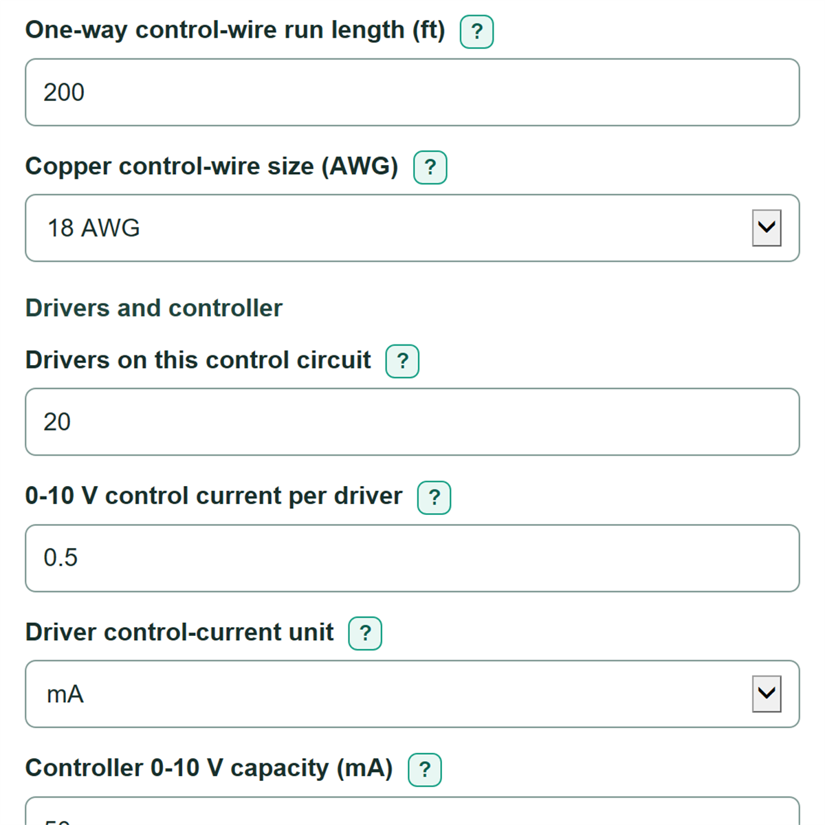
- Enter the One-way control-wire run length from the controller to the farthest driver. Do not double the distance because the calculator includes both control conductors.
- Choose the Copper control-wire size shown on the cable jacket, drawings, or wire schedule.
- Enter Drivers on this control circuit, counting LED drivers rather than fixtures. Enter the driver control current and choose the exact mA or uA unit from its cut sheet.
- Enter the matching Controller 0-10 V capacity in mA. Use its control-output rating, not fixture watts or line current.
- Click Calculate. Check that the planned group fits the safe maximum, then compare the estimated control-wire voltage drop with your project or equipment limit.
Definitions
0-10 V control current: The small current used by a driver and controller on the dimming control pair. It is different from line-side current and fixture power.
mA and uA: Milliamp and microamp. One mA equals 1,000 uA.
AWG: American Wire Gauge, a wire-size system. A smaller AWG number means a larger copper conductor with lower resistance.
Control-wire voltage drop: Voltage lost in the DIM+ and DIM- conductors because the wire has resistance.
Controller-current limit: The largest whole driver count allowed by the controller's stated 0-10 V current capacity.
Wire-drop limit: The largest whole driver count that stays at or below the chosen Allowed control-wire voltage drop (V).
Safe maximum: The lower of the controller-current limit and wire-drop limit.
Common mistakes and quick fixes
Mistake: Entering round-trip distance in One-way control-wire run length.
Fix: Enter only the route from controller to farthest driver. The calculation already includes DIM+ and DIM-.
Mistake: Counting fixtures instead of Drivers on this control circuit.
Fix: Count every LED driver. A fixture with two drivers counts as two.
Mistake: Using fixture watts or branch-circuit amps for 0-10 V control current per driver.
Fix: Copy the 0-10 V dimming-control current from the driver or fixture cut sheet.
Mistake: Typing 150 as mA when the data sheet says 150 uA.
Fix: Choose uA in Driver control-current unit, then enter 150. This is equal to 0.15 mA.
Mistake: Using a wattage rating for Controller 0-10 V capacity.
Fix: Enter the controller channel's matching 0-10 V sink or source capacity in mA.
Mistake: Treating Allowed control-wire voltage drop (V) as a universal rule.
Fix: Replace the planning value with the limit in the project specification or the driver and controller documentation.
Limitations & Key Assumptions / Boundary Conditions
- This is a planning estimate for one copper 0-10 V control pair and one entered one-way route to the farthest driver.
- The wire-resistance estimate is anchored to 14 AWG copper at 0.00326 ohms per foot and scales other listed AWG sizes. Actual cable construction, temperature, splices, terminals, and connections can change resistance.
- The calculation assumes each connected driver has the same entered 0-10 V control current. Mixed driver types or branched runs need a segment-by-segment check.
- The selected allowed drop is a design limit, not a guarantee of dimming behavior. Use the stricter project, controller, or driver requirement. Applicable Signify CertaDrive guidance specifies a 0.1 V maximum dimming-wire voltage drop. [1]
- A passing result checks only steady-state control current and estimated control-wire drop. It does not verify sink versus source compatibility, channel count, polarity, wiring class, line load, inrush, fault conditions, or manufacturer compatibility.
- The estimated full-scale voltage at farthest driver uses 10 V minus the calculated drop. It is not a manufacturer-rated dimming-performance result.
Methodology
Calculation method
The calculator converts the entered driver current to mA. It then multiplies that current by the entered driver count to find planned group control current. The wire calculation uses the entered one-way distance and multiplies by 2 for the outgoing and return control conductors.
driver control current (mA) = entered current x 0.001 when the selected unit is uA
wire resistance (ohms/ft) = resistance per 1,000 ft / 1,000
planned group control current (mA) = drivers x driver control current (mA)
estimated control-wire voltage drop (V) = 2 x one-way length (ft) x wire resistance (ohms/ft) x planned current (mA) x 0.001
The controller-current limit and wire-drop limit are each rounded down separately because part of a driver cannot be connected. The safe maximum is the lower whole-number limit.
controller-current limit = floor(controller capacity (mA) / driver control current (mA))
wire-drop limit = floor(allowed drop (V) / drop per driver (V))
safe maximum drivers = min(controller-current limit, wire-drop limit)
maximum one-way run (ft) = allowed drop (V) / (2 x wire resistance x drivers x driver current (mA) x 0.001)
Worked example
With a 200 ft one-way run, 14 AWG standard annealed copper at 20 C with no resistance override, 20 drivers, 0.5 mA per driver, a 50 mA controller capacity, and a 0.3 V allowed drop, planned control current is 10 mA. Estimated wire drop is 0.01008 V. The controller-current limit is 100 drivers and the wire-drop limit is 595 drivers, so the safe maximum is 100 drivers. The planned group fits these two checks.
Model scope
Blank cable resistance uses NBS Handbook 100, Table 6, standard annealed copper at 20 C: 14/16/18/20/22/24 AWG correspond to 2.52/4.02/6.39/10.1/16.2/25.7 ohms per 1,000 ft. These rounded reference values are not a guarantee for a particular stranded cable or temperature. Enter the actual one-conductor resistance at working temperature to override the table. The earlier 3.26 ohms per 1,000 ft assumption for 14 AWG can be reproduced by entering 3.26. Connections are not included. The 10 V reference is used only to show drop as a percent of 10 V and to estimate voltage at the farthest driver. Equipment documentation can require a lower voltage-drop limit; applicable Signify CertaDrive guidance specifies a 0.1 V maximum dimming-wire voltage drop. [1]
NBS Handbook 100: Copper Wire Tables, Table 6 (20 C)