
Check DALI bus current, separate address limits, cable voltage drop, and the minimum number of DALI lines your design needs.
Advanced options
Table of contents
How to use our DALI Bus Capacity Calculator
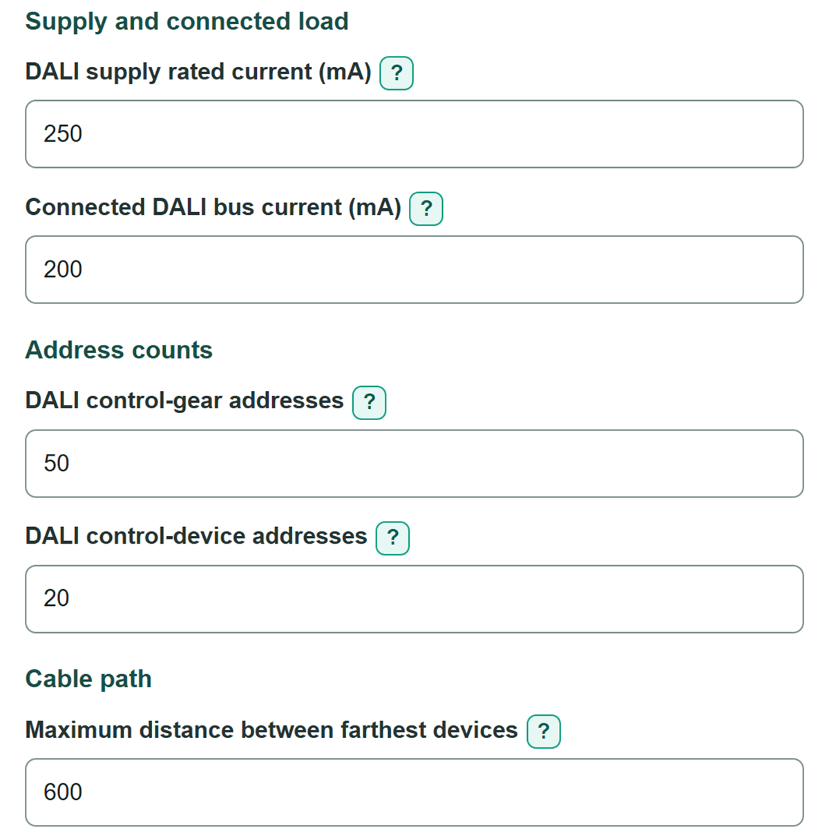
- Enter the nameplate value from the power source in DALI supply rated current and add all connected device demand in Connected DALI bus current.
- Enter drivers and ballasts in DALI control-gear addresses, then enter sensors, wallstations, and similar devices in DALI control-device addresses.
- Enter the longest electrical path between the two farthest bus devices in Maximum distance between farthest devices, choose its unit, and select the copper conductor size from the drawing or cable label.
- Click Calculate, then check DALI line planning status first. A cable redesign result needs a routing or conductor change even if the line count is increased.
- Sanity-check that the displayed cable distance is not total cable purchased, the voltage drop is no more than 2 V, and negative headroom matches any known overload.
Definitions
DALI bus: The two-wire communication and control line that connects DALI devices.
Control gear: Addressed lighting equipment such as a DALI LED driver or ballast. Its addresses are counted separately from control-device addresses.
Control device: An addressed control product such as a sensor, wallstation, or input device.
Bus current: The total current drawn from the DALI line by connected bus-powered devices, entered in milliamps (mA).
Voltage drop: Voltage lost in the two bus conductors over the farthest-device path. This calculator checks the DALI 2 V limit. [1]
Headroom: Usable one-line capacity minus the entered demand. A negative headroom value is the amount over the planned one-line capacity.
Farthest-device distance: The maximum electrical path between the two farthest DALI devices, not the total amount of cable installed.
Common mistakes and quick fixes
Mistake: Entering 0.2 instead of 200 in Connected DALI bus current after copying a 200 mA datasheet value.
Fix: Enter bus current in mA. Use 200 for 200 mA, not 0.2.
Mistake: Using fixture count for DALI control-gear addresses when a fixture has more than one addressed driver.
Fix: Count addressed drivers and ballasts in DALI control-gear addresses.
Mistake: Adding sensors and wallstations to DALI control-gear addresses.
Fix: Enter those addressed controls separately in DALI control-device addresses.
Mistake: Entering total installed cable length in Maximum distance between farthest devices.
Fix: Enter only the longest electrical path between the two farthest DALI devices.
Mistake: Treating a larger Minimum DALI lines needed result as an automatic fix for a cable failure.
Fix: If DALI line planning status says cable redesign needed, also revise the route, supply placement, topology, or Copper conductor size.
Mistake: Leaving planning reserves in place without checking project criteria.
Fix: Review Current kept in reserve (mA) and Addresses kept in reserve for each address group before using the result for a final design.
Limitations & Key Assumptions / Boundary Conditions
- This is a planning screen for one DALI line. It does not replace the device manufacturer instructions, project specifications, commissioning checks, or local electrical-code requirements.
- The cable estimate uses a copper-conductor planning coefficient of 0.020 ohm mm2 per m, a 2 V DALI voltage-drop limit, and a separate 300 m protocol cap. It does not adjust resistance for conductor temperature, terminals, splices, or special cable construction.
- Only the listed copper conductor sizes are modeled. Do not use this result for aluminum, mixed materials, or an unlisted cable size.
- The minimum line count is based on total current and separate control-gear and control-device address counts. It does not determine how devices should be divided, where supplies should be placed, or whether a proposed topology fixes a cable issue.
- Current and address reserves are editable planning policies. Blank reserve fields count as zero reserve, which can make the result less conservative.
- A route over 300 m fails this screening check even at zero or low calculated voltage drop.
Methodology
Capacity calculation
The calculator limits the selected supply to 250 mA, then subtracts the optional current reserve. It separately starts with 64 control-gear addresses and 64 control-device addresses, then subtracts the same optional address reserve from each group. The required line count is the largest count required by current, control gear, or control devices.
usable current (mA) = min(supply rated current, 250) - current reserve
usable addresses per group = 64 - address reserve
minimum lines = max(ceil(bus current / usable current), ceil(gear addresses / usable addresses), ceil(device addresses / usable addresses))
Cable check
The entered distance is converted to meters when needed. The cable calculation models the outgoing and return conductors, which is why it uses a factor of 2. The allowed distance is the lower of the distance allowed by the 2 V drop calculation and the independent 300 m DALI cap. The 2 V, 300 m, 250 mA, and 1.5 mm2 reference boundary comes from the DALI Alliance technical note. [1]
voltage drop (V) = 2 * distance (m) * current (A) * 0.020 / conductor area (mm2)
allowed distance = min(300 m, 2 * conductor area / (2 * current (A) * 0.020))
Worked example
With a 250 mA supply, a 12 mA reserve leaves 238 mA usable. A 200 mA connected load therefore needs one line. With a 9-address reserve, each address group has 55 usable addresses, so 50 control-gear addresses and 20 control-device addresses also fit one line. For 600 ft of path, 200 mA, and 1.5 mm2 copper, the estimated drop is 0.97536 V, so the cable check passes.
Calculation choices
Zero connected current produces 0 V drop and retains the 300 m distance cap. Signed headroom is kept: a negative value shows the amount by which one line exceeds usable current or address capacity. A cable failure takes priority in the status because adding lines alone does not prove that the farthest-device path will pass.