
Enter amps, voltage, one-way distance, wire material, and voltage drop target to estimate a practical wire size.
Advanced options
Table of contents
How to use our Wire Size Calculator
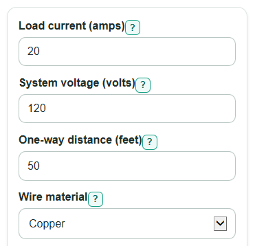
- Enter Load current (amps), System voltage (volts), and One-way distance (feet); use the distance from the source to the load, not the full out-and-back path.
- Choose Wire material and set Max voltage drop (percent); a lower voltage drop target usually means a thicker wire.
- Open Advanced options only if you know the needed Power type, Load duration, Ampacity temperature column (C), or Number display.
- Click Calculate, then read Recommended wire size, Result status, and What controlled the size first.
- Sanity-check the result by comparing Voltage drop, Estimated voltage at the load, and If you use one size larger; if the voltage at the load looks too low, increase voltage, shorten the run, lower current, or ask an electrician.
Definitions
AWG: American Wire Gauge. For AWG sizes, lower numbers mean thicker wire, so 10 AWG is thicker than 12 AWG.
Load current: The amps the circuit is expected to carry while the load is running.
One-way distance: The distance from the power source to the load in one direction. Do not double it before entering it.
Voltage drop: The voltage lost in the wire before power reaches the load. It can be shown as volts or as a percent of the source voltage.
Ampacity: The current a wire size is allowed to carry under the selected table conditions.
Temperature column: The ampacity table column, in degrees C, tied to wire insulation and terminal temperature ratings.
Continuous load: A load expected to run for 3 hours or more; the calculator can use 125 percent of the entered current for this option.
Circular mils: A wire area unit used in the voltage drop formula. Larger circular mil area means less resistance for the same material.
Common mistakes and quick fixes
Mistake: Entering round-trip length in One-way distance (feet) .
Fix: Enter only the distance from the source to the load; the calculator already handles the return path.
Mistake: Using breaker size as Load current (amps) when the actual load is much lower or higher.
Fix: Use the expected load amps for the equipment, unless the circuit is truly being sized from that breaker value.
Mistake: Leaving Max voltage drop (percent) blank or typing a percent sign into a value that should be a number.
Fix: Enter a positive number such as 3, not blank text.
Mistake: Choosing the wrong Wire material because copper and aluminum look interchangeable.
Fix: Select the actual conductor material; aluminum usually needs a larger size than copper for the same run.
Mistake: Ignoring Load duration for equipment that runs 3 hours or more.
Fix: Choose Continuous load, use 125 percent when you want the amp check and voltage drop check to use the adjusted current.
Mistake: Treating Recommended wire size as a final code approval.
Fix: Use it as an estimate, then verify the actual installation with local code, terminal ratings, permits, and a qualified electrician.
Limitations & Key Assumptions / Boundary Conditions
- This is an estimate for simple copper or aluminum conductor runs. It is not a permit, inspection, or code-compliance decision.
- The loaded size range is 14 AWG through 4/0 AWG. If no loaded size passes, the calculator reports that the setup is unsupported instead of guessing beyond the table.
- The voltage drop math uses simplified resistance-only K values for copper and aluminum. Real voltage drop can change with conductor temperature, strand type, conduit, cable type, and AC reactance.
- The calculator does not handle conduit fill derating, ambient temperature correction, bundled conductors, harmonic neutral current, parallel conductors, motor starting voltage drop, or local amendments.
- For DC and single-phase AC, the calculator uses a two-wire out-and-back path. For three-phase AC, it uses the balanced three-phase multiplier.
- The small-conductor protection caps used here keep common copper sizes from being overstated, but final protection rules depend on the actual installation and local code.
- Always check equipment voltage limits, terminal temperature ratings, conductor type, breaker size, grounding, and local rules before buying or installing wire.
Methodology
How the wire is selected
The calculator first changes the entered current into the current used for sizing. Normal loads use the entered current. The continuous load option uses 125 percent of the entered current, which matches the common continuous-load sizing idea in US electrical practice [2].
I_calc = I_load * load_factor
It then checks each loaded standard size from the smallest conductor area to the largest. A size must pass both the amp check and the voltage drop target.
choose first size where ampacity >= I_calc and VD_percent <= max_VD_percent
Voltage drop math
For DC and single-phase AC, the formula uses the one-way distance and multiplies by 2 for the out-and-back current path.
V_drop = 2 * K * I_calc * D_ft / CM
For balanced three-phase AC, the formula uses the square root of 3 instead of 2.
V_drop = sqrt(3) * K * I_calc * D_ft / CM
The calculator uses K = 12.9 ohm-cmil per ft for copper and K = 21.2 ohm-cmil per ft for aluminum. It then compares the volts lost with the source voltage to get percent voltage drop [1].
VD_percent = 100 * V_drop / V_source
V_load = V_source - V_drop
P_loss = V_drop * I_calc
Mini example
For a 20 amp, 120 volt, 50 foot one-way copper single-phase run with a 3 percent target and normal load setting, the amp check allows 12 AWG copper at 20 amps, but 12 AWG is over the voltage drop target. The next larger size, 10 AWG, has 10,380 circular mils, so the voltage lost is about 2.49 V, the voltage drop is about 2.07 percent, the estimated load voltage is about 117.51 V, and the wire heat loss is about 49.71 W. That is why the recommended size is 10 AWG for that example.
What controlled the size
The limiting result is labeled as ampacity, voltage drop, or both. Ampacity controls when the current is the reason thinner wires fail. Voltage drop controls when distance, low voltage, or a tight percent target makes the calculator choose a thicker wire. The next-larger-size comparison reruns the same voltage drop and power loss math for the next thicker loaded size so you can see whether upsizing changes the result enough to matter.