
Estimate water hammer pressure rise from flow and pipe data, then check total pressure against your lowest component rating.
Calculation details
Table of contents
How to use our Water Hammer Surge Pressure and Valve Closure Time Calculator
- Enter the flow just before the valve closes and the actual Pipe inside diameter, not the nominal pipe size.
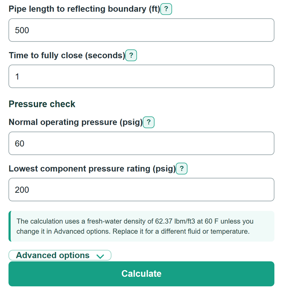
- Enter Pressure-wave speed, the pipe distance to the nearest reflecting boundary, and the effective Time to fully close.
- Add the gauge reading for Normal operating pressure and the lowest applicable pipe, fitting, joint, valve, or equipment rating.
- Select Calculate, then compare estimated total pressure with the signed pressure margin. A negative margin means the estimate is above the entered rating.
- Sanity-check the calculated water velocity and closure classification against your plans or field data. Recheck pipe inside diameter, boundary distance, and effective flow-reduction time if they do not fit the system.
Definitions
Water hammer: A pressure wave caused when flowing water changes speed quickly, such as during valve closure.
Pressure-wave speed: The speed at which a pressure disturbance travels through the filled pipe. It depends on the water and pipe system.
Reflecting boundary: A location, such as a tank, reservoir, pump boundary, or important branch, where the pressure wave is treated as returning in this simplified model.
Critical closure time: Twice the pipe length to the reflecting boundary divided by pressure-wave speed. A closure time at or below this value is rapid in this model.
psig: Gauge pressure in pounds per square inch, measured above local atmospheric pressure.
Joukowsky pressure rise: The maximum rapid-closure pressure-rise estimate based on fluid density, pressure-wave speed, and water velocity change. [2]
Pressure margin below entered rating: Lowest component pressure rating minus estimated total pressure. A negative margin means the estimate exceeds the entered rating.
Common mistakes and quick fixes
Mistake: Entering nominal pipe size as Pipe inside diameter.
Fix: Use the actual inside diameter from pipe data, plans, or a manufacturer table.
Mistake: Using the full project route for Pipe length to reflecting boundary.
Fix: Measure from the closing valve to the nearest important tank, reservoir, pump boundary, open branch, or other reflecting point.
Mistake: Entering total actuator travel as Time to fully close when most flow stops during a shorter part of travel.
Fix: Use the shorter effective time during which flow is actually reduced.
Mistake: Treating Estimated added surge pressure as the pressure already in the pipe.
Fix: Use Estimated total pressure during closure, which adds surge to Normal operating pressure.
Mistake: Comparing the result only with pipe rating and ignoring fittings, joints, valves, or equipment.
Fix: Enter the lowest applicable value in Lowest component pressure rating, including required service or temperature derating.
Mistake: Reading a negative Pressure margin below entered rating as zero margin.
Fix: A negative value means estimated total pressure is above the entered rating and needs engineering review.
Limitations & Key Assumptions / Boundary Conditions
- This is a single-pipe screening calculation. It does not model a full pipe network, branches, repeated reflections, or changing boundary conditions.
- The model assumes water velocity falls from the calculated starting value to zero at closure. It does not model a partial final flow or a detailed valve flow-versus-time curve.
- The gradual-closure reduction uses a simple critical-time ratio. Actual transient pressure can differ because valve behavior is not usually linear.
- Enter the distance from the closing valve to the relevant reflecting boundary, not automatically the full route length.
- Pressure-wave speed can vary greatly with pipe material, wall thickness, restraint, entrained air, and system layout. Replace the example value with project-specific data when available.
- The pressure comparison is only as good as the entered lowest component rating. Account for temperature, service, age, joints, fittings, valves, and any required derating.
- Do not use this screening result alone for safety-critical systems or systems with pump trips, vapor cavities, column separation, surge tanks, air valves, relief devices, or complex operating sequences.
Methodology
Calculation method
The calculator converts Flow rate from gpm to cubic feet per second, calculates the circular pipe flow area from Pipe inside diameter, and divides flow by area to find starting water velocity.
d_ft = d_in / 12
A = π * d_ft^2 / 4
Q_cfs = Q_gpm * 0.002228009259
v = Q_cfs / A
The maximum rapid-closure surge uses the Joukowsky pressure-rise relationship with density in lbm/ft3, wave speed in ft/s, and the US customary force-mass conversion factor.
ΔP_rapid = density * wave_speed * v / 32.174 / 144
The critical closure time is the round-trip wave travel time from the valve to the reflecting boundary and back.
t_critical = 2 * pipe_length / wave_speed
When Time to fully close is at or below the critical time, the added surge equals the rapid-closure estimate. For a longer closure, the calculator multiplies that estimate by the critical time divided by closure time.
closure_factor = 1 if t_close <= t_critical; otherwise t_critical / t_close
ΔP_added = ΔP_rapid * closure_factor
The total and signed rating comparison are then calculated from the normal gauge pressure and entered lowest rating.
P_total = P_operating + ΔP_added
margin = P_rating - P_total
Worked example
With 24.48 gpm in a 2 in inside-diameter pipe, the calculated starting velocity is about 2.50 ft/s. With a wave speed of 4,000 ft/s and a 500 ft boundary distance, critical closure time is 0.25 s. A 1 s closure is gradual, so the rapid estimate of about 134.62 psi is reduced to about 33.65 psi. Adding 60 psig operating pressure gives about 93.65 psig total; against a 200 psig rating, the margin is about 106.35 psi.
Default density
Water density defaults to 62.37 lbm/ft3, the USGS table value for fresh water at 60 F. Replace it when fluid type or temperature differs. [1]