
Calculate a condensate return pipe size or check an existing pipe using load, gauge pressures, flash steam, and a velocity target.
Operating conditions
Pipe screen
Advanced options
Calculation details
Table of contents
How to use our Condensate Return Pipe Size and Flash Steam Velocity Calculator
- Choose "Choose a pipe size" for a new segment or "Check an existing pipe" for a proposed or installed pipe.
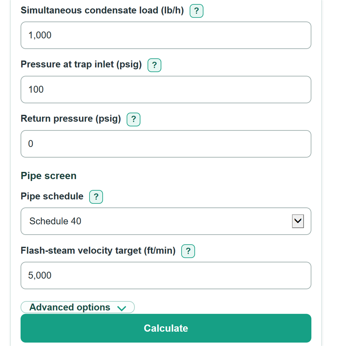
- Choose the Pipe segment type, then enter the simultaneous condensate load carried by this segment in lb/h.
- Enter Pressure at trap inlet and Return pressure in psig; use 0 psig for a return vented to the atmosphere.
- Choose Pipe schedule, enter the Flash-steam velocity target, and choose Existing nominal pipe size when checking a pipe.
- Click Calculate, then compare the calculated velocity and Velocity target margin with the target; a passing velocity screen still needs a separate piping design check.
Definitions
Condensate: Hot liquid water formed when steam gives up heat.
Flash steam: Steam that forms when hot condensate enters a lower-pressure return system.
psig: Gauge pressure, measured above atmospheric pressure. A vented return is 0 psig.
Nominal pipe size (NPS): The named pipe size, such as 1-1/4 in. It is not the same as the actual inside diameter.
Pipe schedule: A wall-thickness designation. Schedule 40 and Schedule 80 of the same NPS have different inside diameters.
Flash-steam velocity target: The selected maximum velocity used for this screening calculation, in ft/min.
Velocity target margin: The target minus calculated velocity, divided by the target. A positive value is below the target; a negative value is above it.
The stored Schedule 40 and Schedule 80 nominal-size and inside-diameter table is based on Spirax Sarco condensate line sizing technical information. [1]
Common mistakes and quick fixes
Mistake: Entering boiler capacity as Simultaneous condensate load (lb/h) even though only part of the plant drains into this segment.
Fix: Add only the loads that can discharge into this pipe at the same time.
Mistake: Using boiler-header pressure for Pressure at trap inlet (psig) after a control valve reduces the pressure.
Fix: Use the operating pressure at the trap inlet from the local gauge, drawing, or control-valve outlet condition.
Mistake: Entering 14.7 for Return pressure (psig) when the return is vented.
Fix: Enter 0 because psig is gauge pressure, not absolute pressure.
Mistake: Treating Existing nominal pipe size (in) as a measured inside diameter.
Fix: Select the marked nominal size and Pipe schedule; the calculator uses their stored inside diameter.
Mistake: Treating a passing Velocity screening status as proof that the piping layout is acceptable.
Fix: Also check trap backpressure, two-phase pressure drop, slope, lifts, flooding, and waterhammer risk.
Limitations & Key Assumptions / Boundary Conditions
- This is a simplified velocity screen for trap discharge lines and common dry return headers. It does not model pumped, flooded, or rising return arrangements.
- Pressures must be from 0 through 150 psig, and Pressure at trap inlet must be greater than Return pressure. These are the supported calculator boundaries.
- The flash estimate uses linearly interpolated saturated-steam table properties and a fixed liquid specific volume of 0.017 ft3/lb. Use project steam-property methods when higher accuracy is needed.
- Subcooling below saturation reduces the estimated flash amount. Leave it blank or enter 0 only when saturated-condensate behavior is a suitable assumption.
- A passing velocity result does not calculate two-phase pressure drop, trap backpressure, pipe slope, vertical lift, drainage, fittings, erosion, noise, or waterhammer.
- The size scan is limited to the stored Schedule 40 and Schedule 80 steel-pipe nominal sizes from 1/2 in through 12 in. A larger calculated bore needs separate design work.
Methodology
Steam properties and flash calculation
Saturated liquid enthalpy hf, latent heat hfg and steam specific volume vg come from the Spirax Sarco dry saturated steam table (TI-GCM-01, pages 1–2). The stored table covers 0–10.5 bar gauge; linear interpolation is used within it. Calculator inputs remain limited to 0–150 psig. Divide psig by 14.503773773 to obtain bar gauge. Divide kJ/kg by 2.326 for Btu/lb; multiply m3/kg by 16.018463374 for ft3/lb.
flash_fraction = max(0, (hf_in - subcooling_f - hf_return) / hfg_return)
Subcooling uses the approximate liquid heat capacity of 1 Btu/(lb deg F). Blank means zero. The remaining liquid volume uses 0.017 ft3/lb.
flow_cfm = load_lbh * (flash_fraction * vg_return + (1 - flash_fraction) * 0.017) / 60
required_bore_in = 12 * sqrt(4 * flow_cfm / (pi * target_ftmin))
The first stored Schedule 40 or 80 bore meeting the target is selected. Check mode evaluates the selected existing bore. Zero load gives zero flow; the flash fraction is never below zero.
Worked example
At 1,000 lb/h, 100 psig inlet, 0 psig return, no subcooling and a 5,000 ft/min target, the steam table gives an inlet liquid enthalpy of about 719.11 kJ/kg. Flash is 13.2946% by mass and combined flow is about 59.66 ft3/min. The required bore is 1.4791 in. Schedule 40 selects 1-1/2 in NPS (1.610 in bore), at about 4,220 ft/min.
Limits
This is a velocity screen for trap discharge and dry headers, not a full piping design. It does not model two-phase pressure drop, fittings, lift, drainage, waterhammer or trap backpressure. Use project-specific methods for detailed design and strongly subcooled liquid.