
Check one PoE switch against your lighting fixture schedule for switch watts, powered ports, and per-fixture PoE type compatibility.
Fixture schedule
Advanced options
Calculation details
Table of contents
How to use our PoE Lighting Power Budget and Switch Capacity Calculator
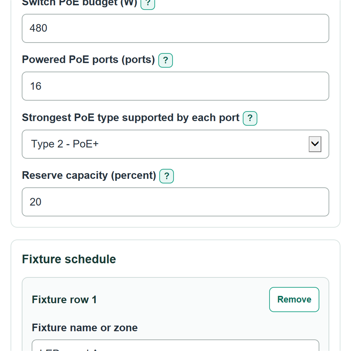
- Copy the manufacturer-stated total into Switch PoE budget, then enter the count in Powered PoE ports.
- Choose the strongest type available in Strongest PoE type supported by each port, based on the ports assigned to lighting.
- Enter your planned buffer in Reserve capacity, then add each fixture model or zone with its quantity, maximum input power, and required PoE type.
- Use Add fixture for every fixture group with different watts or a different PoE type, then select Calculate.
- Read PoE lighting capacity check first, then confirm that switch budget remaining and powered ports left are not negative.
Definitions
PSE: Power sourcing equipment, meaning the switch port that sends PoE power.
PD: Powered device, meaning the light fixture or PoE driver receiving power.
PoE type: The power level category used by a switch port and fixture. Higher types can provide more power per port.
PSE allocation: Conservative switch-side watts reserved for a fixture based on its selected PoE type.
PD-side maximum power: The highest power available at the fixture under the selected PoE type; it is used to check that the entered fixture watts fit that type.
Reserve capacity: Extra switch capacity added to the calculated allocation for future changes or project policy.
Common mistakes and quick fixes
Mistake: Entering a per-port rating or multiplying ports by watts in Switch PoE budget.
Fix: Copy the manufacturer-stated total switch PoE budget in W.
Mistake: Counting every physical network jack as Powered PoE ports.
Fix: Count only ports that can supply PoE, then enter shared-device commitments in PoE ports already reserved.
Mistake: Using a dimmed or typical value for Maximum fixture input power.
Fix: Use the maximum PD-side input power from the fixture or PoE driver cut sheet.
Mistake: Selecting Type 2 - PoE+ for a fixture whose Maximum fixture input power is over 25.5 W.
Fix: Correct the fixture watts or choose the supported stronger PoE type required by fixture.
Mistake: Treating a negative Switch budget remaining after reserve as zero.
Fix: Keep the signed result; a negative number is the additional switch budget needed after the chosen reserve.
Limitations & Key Assumptions / Boundary Conditions
- This checks one switch against the entered fixture schedule at the same time. It does not calculate electricity use, dimming energy savings, switch idle power, UPS runtime, or operating cost.
- The switch budget is treated as the manufacturer-stated total PoE budget. Do not subtract switch electronics power unless the manufacturer defines the published budget that way.
- Each fixture is assumed to use one powered port. Multi-port fixtures, daisy-chained devices, injectors, and midspans need a separate design review.
- The calculation uses the selected PoE type's conservative PSE allocation, not the entered fixture watts, for the switch budget. Fixture watts are checked against the selected type's PD-side limit.
- Cable length, cable construction, temperature, bundling, connector condition, and fixture-specific startup behavior are not modeled. Confirm the actual fixture and cabling requirements before installation.
- Reserve capacity is a project-planning choice. It is not treated as a universal code requirement.
Methodology
Calculation method
For each fixture row, the calculator adds the fixture quantity to the powered-port count and multiplies quantity by maximum fixture input power to report the connected PD-side fixture load.
ports needed = sum of fixture quantities
connected fixture maximum load = sum of (quantity x maximum fixture input power)
The switch-side allocation uses the selected fixture PoE type, not the entered PD-side watts. The type allocations used are 15.4 W for Type 1, 30 W for Type 2, 60 W for Type 3, and 90 W for Type 4. The matching maximum PD-side power limits are 12.95 W, 25.5 W, 51 W, and 71.3 W. Cisco's UPOE+ reference summarizes the Type 1 through Type 4 PSE and powered-device power levels used by this table. [1]
PoE allocation before reserve = sum of (quantity x PSE allocation for fixture PoE type)
switch budget needed with reserve = PoE allocation before reserve x (1 + reserve capacity / 100)
switch budget remaining after reserve = switch PoE budget - switch budget needed with reserve
powered ports left = powered PoE ports - PoE ports already reserved - ports needed
Status rules
Fail means the raw switch allocation exceeds the switch budget, there are too few powered ports, a fixture exceeds its selected type's PD limit, or the switch supports a weaker type than a fixture requires. Caution means the raw allocation fits, but the chosen reserve does not. Pass means all of those checks fit.
Worked example
Eight Type 2 fixtures use 8 ports. Their connected maximum fixture load is 8 x 18 W = 144 W. Their Type 2 switch allocation is 8 x 30 W = 240 W. With 20 percent reserve, the required switch budget is 240 x 1.20 = 288 W. On a 480 W, 16-port Type 2 switch with no reserved ports, 192 W and 8 powered ports remain.
Calculation choices
Blank PoE ports already reserved counts as 0. Negative remaining watts and ports are kept as signed shortfalls rather than changed to zero. Number display changes only how values are shown, not the calculation.