
Check whether an OM3 or OM4 one-way fiber route fits its active reach limits and see the remaining distance margin.
Advanced options
Modal bandwidth check
Optical loss check
Calculation details
Table of contents
How to use our Multimode Fiber Bandwidth and Maximum Reach Calculator
- Choose a Reach limit source: use the planning profile for an early estimate, or choose your optic's published limit.
- Select the Installed fiber type from the cable jacket, reel label, or installation record.
- Enter the full One-way cable route length (ft), including patch cords, slack, risers, and turns.
- If using your optic's limit, enter its Published maximum channel length (m) from the exact manufacturer datasheet.
- Click Calculate, then check the planned route check, remaining distance margin, and limit controlling the answer. A positive margin means the route is shorter than every active limit.
Definitions
OM3 and OM4: Grades of 50/125 micrometer multimode fiber. The channel should be treated as the lowest grade present.
One-way cable route: The end-to-end cable path from transmitter to receiver, including patch cords and slack.
Effective modal bandwidth (EMB): A fiber bandwidth-distance value in MHz km at a stated wavelength. It is not the same as Ethernet data rate.
Modal-bandwidth reach limit: The route length allowed by dividing effective modal bandwidth by the optic's required modal bandwidth.
Optical budget: The loss allowance in dB between the transmitter and receiver limits.
Fixed channel loss: Connector, cassette, and splice loss that does not increase as cable length increases.
Engineering safety margin: Optical budget deliberately held back for a project requirement or future uncertainty.
Remaining distance margin: Maximum supported one-way reach minus the planned one-way route. A negative value means the route is too long.
Common mistakes and quick fixes
Mistake: Using straight-line building distance for One-way cable route length (ft).
Fix: Measure the installed cable path and include risers, slack, patch cords, and pathway turns.
Mistake: Choosing OM4 for Installed fiber type when part of the channel is OM3.
Fix: Select the lowest known fiber grade anywhere in the channel.
Mistake: Entering an optic data rate into Published maximum channel length (m).
Fix: Copy the supported channel length in meters for the exact optic and fiber type.
Mistake: Typing a Gbps data rate into Optic's required modal bandwidth (MHz).
Fix: Leave the field blank unless the optic documentation states a required modal bandwidth in MHz.
Mistake: Entering transmitter power or receiver sensitivity in dBm as Minimum optical budget (dB).
Fix: Enter the stated link budget in dB, or calculate the usable difference between the signed dBm specifications first.
Mistake: Counting full measured channel loss again in Measured fixed channel loss (dB) while also using Fiber attenuation (dB per km).
Fix: Use fixed loss only for non-fiber losses, or use a loss worksheet that avoids counting the same fiber loss twice.
Limitations & Key Assumptions / Boundary Conditions
- The planning profile is an estimate for the stated fiber grade and 850 nm conditions. It is not a certification result or a guarantee for every vendor optic.
- A pass means only that the route fits the active limits entered in this calculator. It does not confirm connector quality, polarity, cleanliness, installation workmanship, or interoperability.
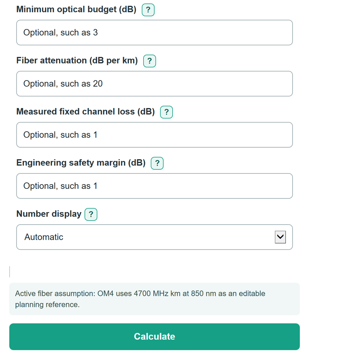
- The modal-bandwidth limit appears only when an Optic's required modal bandwidth (MHz) is entered. The optical-loss limit appears only when all four optical-loss fields are complete.
- Effective modal bandwidth and fiber attenuation depend on wavelength and the specific cable. Replace suggested values with the applicable fiber and optic datasheet values when available.
- Measured fixed channel loss must not include fiber attenuation if Fiber attenuation (dB per km) is also used, or loss will be counted twice.
- At a route length of 0 ft, available modal bandwidth is not calculated because dividing by zero distance would be meaningless.
Methodology
How the reach is chosen
The calculator converts the entered one-way route from feet to meters. It then starts with either the selected planning-profile limit or the Published maximum channel length (m) for the optic. Optional modal-bandwidth and optical-loss limits are calculated separately. The shortest active limit becomes Maximum supported one-way reach.
planned route (m) = one-way cable route length (ft) * 0.3048
modal-bandwidth reach (m) = effective modal bandwidth (MHz km) / required modal bandwidth (MHz) * 1000
optical-loss reach (m) = (optical budget - fixed channel loss - safety margin) / fiber attenuation * 1000
maximum supported reach (m) = shortest active reach limit
remaining distance margin (m) = maximum supported reach (m) - planned route (m)
Worked example
For a 300 ft route, the metric route length is 91.44 m. If the selected published application reach is 150 m and no optional limits are active, the maximum supported reach is 150 m and the remaining distance margin is 58.56 m. If an active modal-bandwidth or optical-loss calculation produces a smaller reach, that smaller value controls instead.
Calculation conditions
The optical-loss calculation uses a complete set of Minimum optical budget (dB), Fiber attenuation (dB per km), Measured fixed channel loss (dB), and Engineering safety margin (dB). It stops with an error if the budget does not exceed fixed loss plus margin, because no positive fiber-distance allowance remains. Optional blank fields do not constrain the answer. Negative distance margin is retained so a failed route shows how far it exceeds the controlling limit.