
Estimate equal-span DWDM EDFA cascade OSNR or find the widest amplifier spacing that meets your route's target OSNR.
Advanced options
Table of contents
How to use our DWDM EDFA Cascade OSNR and Amplifier Spacing Calculator
- Choose Check planned spacing to test a proposed design, or Find maximum spacing to solve for the widest equal spacing that reaches Target OSNR.
- Choose kilometers or miles, then enter the installed Route length; in check mode, also enter Planned amplifier spacing.
- Enter per-channel optical values from the power plan and EDFA data: Launch power per channel, EDFA noise figure, and Fiber attenuation.
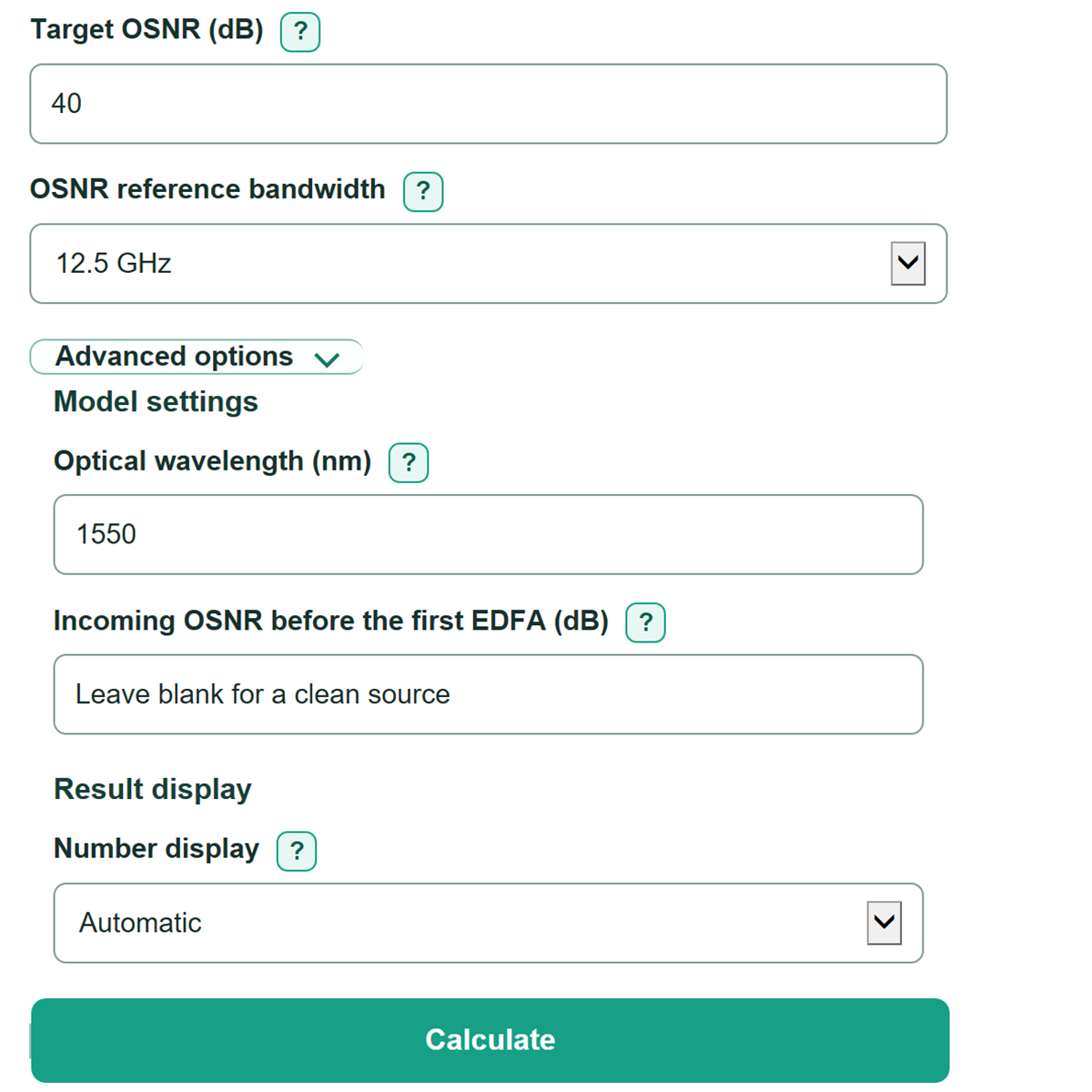
- Enter the required Target OSNR and choose the matching OSNR reference bandwidth. Open Advanced options only if you need a different wavelength or an existing incoming OSNR.
- Click Calculate. Check that the estimated OSNR and target use the same reference bandwidth, then read the signed OSNR margin above target: positive passes this model, while negative is below target.
Definitions
OSNR: Optical signal-to-noise ratio. It compares channel signal power with optical noise power; a higher value is better.
dB: A logarithmic ratio unit. OSNR, noise figure, span loss, and OSNR margin are shown in dB.
dBm: Optical power referenced to 1 milliwatt. The launch-power input must be per channel, not combined DWDM power.
EDFA noise figure: A dB measure of noise added by an erbium-doped fiber amplifier. The model uses the same noise figure for every modeled stage.
ASE noise: Amplified spontaneous emission noise generated by an optical amplifier. The model adds the ASE contribution from each EDFA stage.
OSNR reference bandwidth: The noise bandwidth used to report OSNR. A target and calculated OSNR can be compared only when they use the same bandwidth.
OSNR margin above target: Estimated end-of-route OSNR minus Target OSNR. A positive margin is above target; a negative margin is below it.
Common mistakes and quick fixes
Mistake: Entering total DWDM composite power in Launch power per channel.
Fix: Enter one channel's power in dBm, taken from the channel power plan or measurement.
Mistake: Comparing Estimated end-of-route OSNR with a requirement measured at a different OSNR reference bandwidth.
Fix: Choose the same bandwidth stated beside the transponder requirement or OSNR measurement.
Mistake: Treating Fiber attenuation as the full real-world span loss when connectors, splices, or nodes add loss.
Fix: Use an average attenuation that accounts for the applicable route loss, or use a detailed engineering budget outside this equal-span estimate.
Mistake: Entering a desired site-to-site distance as Planned amplifier spacing and expecting every modeled span to have that exact length.
Fix: The calculator rounds up Modeled EDFA stages and divides the route evenly, so check Equal spacing used in the estimate.
Mistake: Leaving an old upstream value in Incoming OSNR before the first EDFA (dB) for a clean-launch estimate.
Fix: Leave that field blank when source noise is intentionally ignored; otherwise enter an upstream OSNR at the selected reference bandwidth.
Limitations & Key Assumptions / Boundary Conditions
- This is an equal-span planning model. It divides the route into equal distances and applies one Fiber attenuation value and one EDFA noise figure to every stage.
- It models distance-based fiber loss only. Connector, splice, ROADM, node, patch-panel, repair-margin, and transient losses are not separately modeled.
- The EDFA gain is assumed to exactly replace the modeled loss per equal span. Gain tilt, saturation, channel loading, gain-control behavior, and per-channel power tilt are outside the calculation.
- Blank Incoming OSNR before the first EDFA (dB) means a clean source with no incoming noise contribution. Enter a measured upstream OSNR when the route begins after an existing optical section.
- The 0.1 nm reference-bandwidth choice uses a narrow-band wavelength-to-frequency conversion at Optical wavelength (nm). Use the wavelength and bandwidth associated with the actual requirement.
- A passing OSNR margin is not a complete optical design approval. Check nonlinear effects, dispersion, FEC requirements, receiver performance, site constraints, and vendor design rules separately.
Methodology
Equal-span cascade model
The route is split into equal modeled EDFA stages. In Check planned spacing mode, the stage count is rounded up so no modeled span exceeds Planned amplifier spacing. In Find maximum spacing mode, the calculator tests whole stage counts beginning at one and keeps the first count that reaches Target OSNR.
N = ceil(route length in km / planned spacing in km)
equal spacing in km = route length in km / N
span loss in dB = fiber attenuation in dB/km * equal spacing in km
Noise and OSNR calculation
Launch power is converted from dBm to watts. Noise figure is converted from dB to a linear noise factor. Each EDFA is assumed to provide gain equal to its modeled span loss, then its ASE noise is calculated over the selected noise reference bandwidth. The same ASE contribution is added for each modeled stage. This is a simplified polarization-inclusive EDFA ASE planning calculation. [1]
signal power in W = 10^((launch power in dBm - 30) / 10)
noise factor = 10^(EDFA noise figure in dB / 10)
ASE per stage in W = noise factor * h * optical frequency * (gain - 1) * reference bandwidth
total noise in W = incoming noise + N * ASE per stage
estimated OSNR in dB = 10 * log10(signal power / total noise)
OSNR margin in dB = estimated OSNR - target OSNR
Reference bandwidth and incoming noise
The 12.5 GHz setting uses 12,500,000,000 Hz. For the 0.1 nm setting, the calculator converts wavelength width to frequency width using the speed of light and the entered optical wavelength. [2] If Incoming OSNR before the first EDFA (dB) is blank, incoming noise is set to zero. Otherwise, it is converted to watts and added to accumulated EDFA noise.
0.1 nm bandwidth in Hz = c * 0.1 nm / (wavelength in nm)^2
Worked example
With a 200 km route, 50 km planned spacing, 0 dBm launch power per channel, 5 dB noise figure, 0.20 dB/km attenuation, 12.5 GHz reference bandwidth, and a clean source, the model uses 4 stages. Each equal span is 50 km with 10 dB modeled loss. The estimated end-of-route OSNR is about 37.39 dB; against a 35 dB target, the margin is about +2.39 dB.
Calculation boundaries
Distances must be greater than zero. Check mode also requires a positive Planned amplifier spacing. The solver stops with an error if Target OSNR is above the best value this equal-span model can reach under the entered assumptions. Negative launch power and negative OSNR margin remain valid values and are not forced to zero.