
Add each AV-over-IP stream group to check uplink traffic, endpoint ports, and switch capacity before you choose hardware.
Candidate switch
Advanced options
Calculation details
Table of contents
How to use our AV-over-IP Network Bandwidth and Switch Capacity Calculator
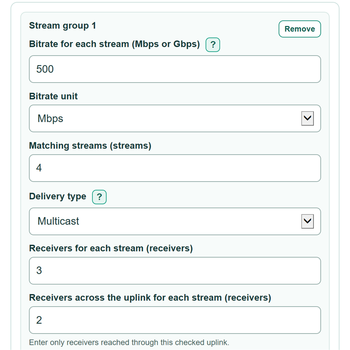
- For each matching stream group, enter Bitrate for each stream, choose its Bitrate unit, and enter Matching streams.
- Choose Delivery type, then enter total Receivers for each stream and only the Receivers across the uplink for each stream.
- Enter the candidate switch details: Speed of each uplink link, Uplink links in the LAG, Ports available for AV endpoints, and Published switching capacity.
- Open Advanced options if needed to change Planned usable capacity (%); the editable 80% setting reserves capacity for planning.
- Click Calculate, then check that all three remaining-capacity values are zero or higher and that the largest-stream member percentage is no more than 100%.
Definitions
AV-over-IP: Audio and video sent as network data between transmitters, receivers, and switches.
Bitrate: The data rate for one stream. This calculator accepts Mbps or Gbps for each stream group.
Multicast: A delivery type where one stream copy crosses the checked uplink when one or more far-side receivers need it.
Unicast: A delivery type where each far-side receiver needs its own stream copy across the checked uplink.
LAG: Link aggregation group. It combines multiple physical uplink links for aggregate traffic, while one stream should still fit on one member link.
Switching capacity: The published switch-fabric or backplane capacity copied from the switch data sheet.
Planned usable capacity: The percent of nominal uplink and switching capacity used for planning. It is an allowance, not a measured protocol-overhead value.
Full-duplex switch-fabric demand: A conservative estimate equal to twice receiver-delivery traffic for comparison with a published full-duplex switching-capacity figure.
Common mistakes and quick fixes
Mistake: Entering 500 while Bitrate unit is set to Gbps when the encoder says 500 Mbps.
Fix: Set Bitrate unit to Mbps, or enter 0.5 with Gbps selected.
Mistake: Using all Receivers for each stream as Receivers across the uplink for each stream even when some receivers are local.
Fix: Count only receivers reached through the specific uplink being checked.
Mistake: Treating a multicast stream as one uplink copy for every far-side receiver.
Fix: Select Multicast for Delivery type ; one or more far-side receivers then use one uplink copy in this model.
Mistake: Entering the combined LAG speed as Speed of each uplink link.
Fix: Enter one physical member's speed and enter the number of members in Uplink links in the LAG.
Mistake: Counting uplink ports or unusable media types in Ports available for AV endpoints.
Fix: Count only remaining ports that have the needed speed and media for AV transmitters and receivers.
Mistake: Copying a backplane value in Tbps directly into Published switching capacity.
Fix: Convert Tbps to Gbps first. For example, 1.2 Tbps is 1,200 Gbps.
Limitations & Key Assumptions / Boundary Conditions
- The calculation uses entered stream bitrates. It does not measure real network traffic, packet overhead, control traffic, burst behavior, or other non-AV traffic.
- The planned-capacity percentage is a design allowance. It is not a measured network-overhead percentage, so replace it with the project policy when one exists.
- For a LAG, the calculator checks aggregate capacity and separately checks whether the largest active stream fits on one physical member. Actual flow distribution depends on the hashing method and traffic pattern.
- Endpoint-port demand assumes every listed transmitter and receiver connects to the candidate switch. It excludes uplink ports and relies on the entered count of suitable available ports.
- The fabric comparison uses twice receiver-delivery traffic as a conservative full-duplex planning estimate. Confirm that the published switching-capacity specification uses a compatible convention.
- The checked uplink covers only receivers placed across that one uplink. Check each uplink separately in a multi-switch design.
- PoE budget, VLAN setup, IGMP behavior, latency, port media compatibility, and device-specific limits are outside this calculation.
Methodology
Calculation method
Each stream row is converted to Mbps, then multiplied by its number of matching streams. A Mbps value is divided by 1,000 to express traffic in Gbps.
source traffic (Gbps) = SUM(stream bitrate in Mbps * matching streams) / 1000
For uplink traffic, multicast contributes one copy when at least one receiver is across the checked uplink. Unicast contributes one copy for every receiver across that uplink.
uplink copies = multicast: 1 when far-side receivers > 0, otherwise 0; unicast: far-side receivers
uplink traffic (Gbps) = SUM(stream bitrate in Mbps * matching streams * uplink copies) / 1000
Required endpoint ports include one transmitter and the entered receiver count for every active stream.
endpoint ports needed = SUM(matching streams * (1 + receivers for each stream))
The switch-fabric estimate counts receiver delivery and multiplies it by two for a full-duplex comparison.
fabric demand (Gbps) = 2 * SUM(stream bitrate in Mbps * matching streams * receivers for each stream) / 1000
Usable uplink capacity is the speed of one physical link times the number of LAG links, then multiplied by Planned usable capacity (%). The same percentage is applied to the published switching capacity. Each remaining-capacity result is usable capacity minus planned demand, so a negative number is a shortage.
usable capacity = nominal capacity * planned usable capacity / 100
capacity remaining = usable capacity - planned demand
Worked example
Suppose four multicast streams run at 500 Mbps each, each has three receivers, and two receivers per stream are across the uplink. Source traffic is 2.0 Gbps. Uplink traffic is also 2.0 Gbps because multicast uses one far-side copy per stream. Endpoint-port demand is 16 ports, and the estimated fabric demand is 12.0 Gbps. With two 10 Gbps uplinks and an 80% planned limit, usable uplink capacity is 16 Gbps, leaving 14 Gbps.
Status rule
Fail means at least one nominal hardware limit is exceeded. Caution means nominal capacity is enough but the selected planned reserve is exceeded. Pass means uplink capacity, endpoint ports, and switching capacity all meet the selected planned limit.