
Estimate per-bolt clamp force from tightening torque or find a preliminary torque from a target preload for supported inch fasteners.
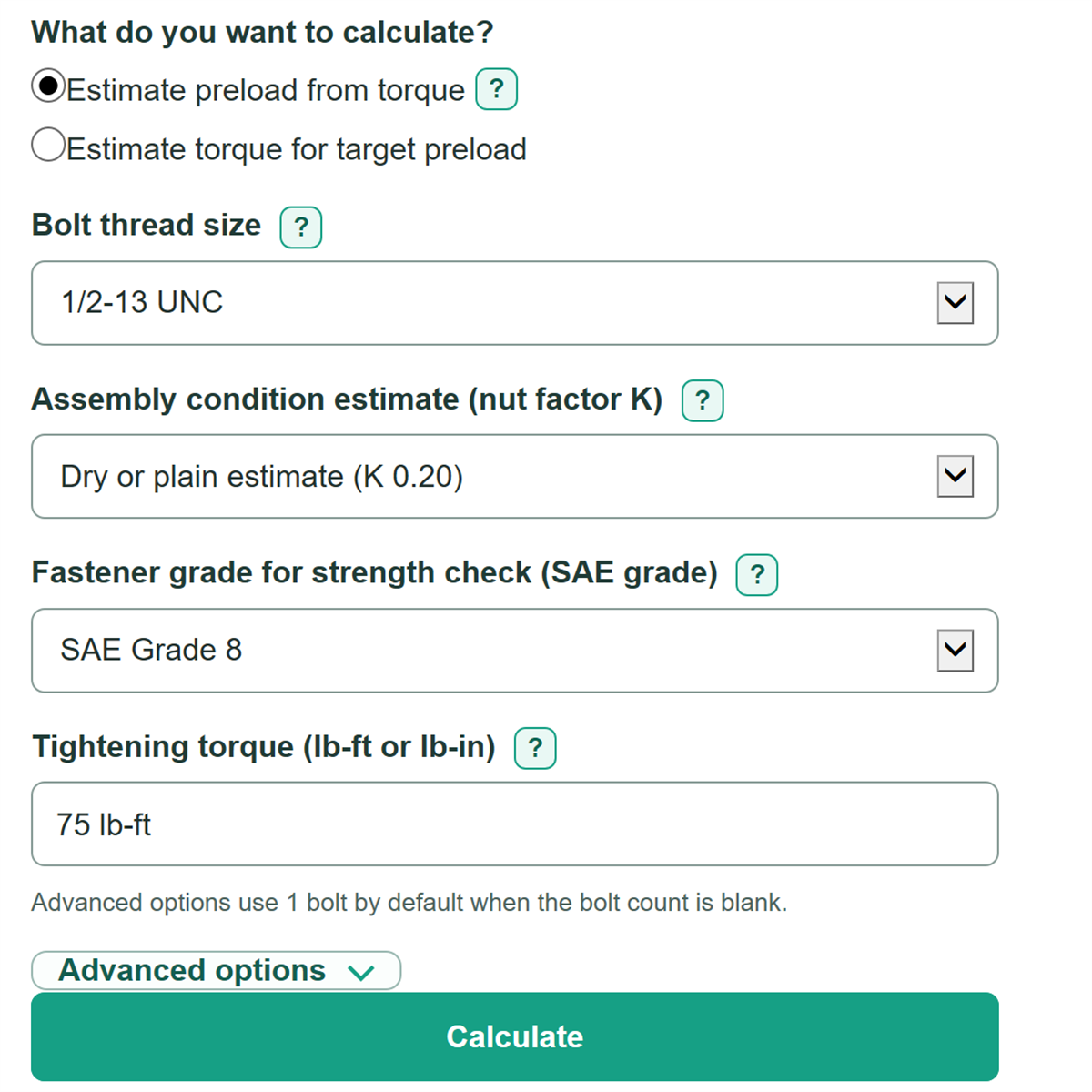
Advanced options use 1 bolt by default when the bolt count is blank.
Advanced options
Torque-derived force is a planning estimate because friction can change the actual preload.
This assumes equal preload in every bolt. Bolt count does not change the per-bolt result.
This is a simplified reference estimate, not a formal compliance check.
K represents combined thread and bearing friction in the short-form equation.
Table of contents
How to use our Bolt Torque, Preload and Clamp Force Calculator
- Choose whether you know the tightening torque or the target preload per bolt.
- Select the full Bolt thread size from the drawing, package, or thread gauge, then choose the closest Assembly condition estimate.
- Select Fastener grade for strength check if you know the head marking; otherwise choose the option to skip the check.
- Enter Tightening torque with lb-ft or lb-in, or enter Target preload per bolt in lbf, then select Calculate.
- Check that the Nut factor K used matches the actual coating and lubricant. Treat Estimated proof-load use above 100 percent as an overload indication, not an approval.
Definitions
Preload or clamp force: The compressive force a tightened bolt is estimated to create in one joint.
Tightening torque: The twisting input used to tighten the bolt, entered here in lb-ft or lb-in.
Nut factor K: A unit-free friction estimate that combines friction in the threads and under the nut or bolt head. A smaller K produces more estimated preload from the same torque.
Nominal diameter D: The stated bolt diameter in inches, such as 0.500 inch for a 1/2-inch bolt.
Tensile stress area: The effective threaded cross-sectional area used to estimate proof load. Thread pitch changes this area.
Proof load: Tensile stress area multiplied by proof strength. The supported thread areas and SAE Grade 5 and Grade 8 reference strengths use NASA fastener reference data [1].
Estimated proof-load use: Per-bolt clamp force divided by estimated proof load, shown as a percent.
Common mistakes and quick fixes
Mistake: Entering a torque without noticing that Tightening torque treats a bare number as lb-ft.
Fix: Type the unit when needed, such as "75 lb-ft" or "900 lb-in."
Mistake: Selecting a Bolt thread size by diameter only and missing the thread series.
Fix: Match the full designation, such as 1/2-13 UNC or 1/2-20 UNF, because the strength check uses its thread stress area.
Mistake: Using a dry torque specification after adding oil, coating, or anti-seize.
Fix: Choose the Assembly condition estimate that fits the actual assembly, or enter a documented Tested nut factor K.
Mistake: Entering the combined joint load in Target preload per bolt.
Fix: Enter the force for one bolt only; use Bolts in the joint to calculate Estimated total joint clamp force.
Mistake: Treating Estimated proof-load use as a certified pass or installation instruction.
Fix: Use the Fastener grade for strength check or Documented proof strength (psi) only as a simplified planning check, and follow the applicable procedure for the joint.
Limitations & Key Assumptions / Boundary Conditions
- This is a short-form torque-tension estimate for supported UNC and UNF inch fastener designations only. It is not a bolt installation specification.
- The calculation assumes K fits the actual fastener, coating, lubricant, bearing surface, and joint setup. Friction changes can cause actual preload to differ substantially from the estimate.
- The proof-load calculation is a simplified room-temperature reference check using the selected SAE grade or a documented proof strength. It does not certify compliance, fatigue life, yield, or joint safety.
- Total joint clamp force assumes equal preload in every bolt. It does not model joint stiffness, load distribution, embedment, relaxation, bolt stretch, or external loading.
- Do not use a dry or plain torque estimate for lubricated, coated, anti-seize-treated, safety-critical, structural, aerospace, or other controlled assemblies without the applicable tested procedure.
- A Bolts in the joint value of 0 intentionally makes Estimated total joint clamp force zero while leaving the per-bolt estimate unchanged.
Methodology
Calculation method
The calculator uses the common short-form torque-tension relationship. Torque is converted to lb-in before the preload calculation; 1 lb-ft equals 12 lb-in.
T = K x D x F
T is tightening torque in lb-in, K is the nut factor, D is nominal bolt diameter in inches, and F is per-bolt clamp force in lbf.
F = T / (K x D)
This form is used when estimating clamp force from entered torque.
T = K x D x F
This form is used when estimating required torque from Target preload per bolt. The calculator then divides lb-in by 12 to show lb-ft.
Strength check
For a selected grade or Documented proof strength (psi), the calculator looks up the supported thread tensile stress area and estimates proof load from the reference values in NASA RP-1228. The same source supports the supported Unified thread areas and SAE Grade 5 and Grade 8 proof strengths [1].
Proof load = tensile stress area x proof strength
Estimated proof-load use = per-bolt clamp force / proof load x 100
If no grade and no documented proof strength are supplied, the proof-load results are omitted. Total joint clamp force is per-bolt clamp force times Bolts in the joint.
Worked example
For a 1/2-13 bolt at 75 lb-ft, the torque becomes 900 lb-in. With K = 0.20 and D = 0.500 inch, estimated per-bolt clamp force is 900 / (0.20 x 0.500) = 9,000 lbf. With SAE Grade 8 reference proof strength of 120,000 psi and stress area of 0.1419 square inches, estimated proof load is 17,028 lbf, so estimated proof-load use is about 52.85 percent.
Assumptions and limits
The selected assembly condition supplies K = 0.20 for dry or plain and K = 0.15 for a typical steel-on-steel estimate. A valid Tested nut factor K replaces that estimate. These values are planning inputs, so a documented torque-tension test value is preferable when available. The method does not model separate thread and bearing friction, joint stiffness, relaxation, temperature effects, or load sharing.