
Check whether one dedicated device load fits a breaker, with continuous-load and optional long wire-run checks.
Table of contents
How to use our Dedicated Circuit Load Calculator
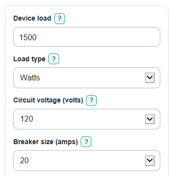
- Enter the Device load from the nameplate or manual, then set Load type to Watts or Amps to match that number.
- Choose the Circuit voltage, Breaker size, and whether the device Runs 3 hours or more at a time?
- Open Advanced options only if you want to adjust Power factor for watt loads or estimate voltage drop using One-way wire length and Copper wire size.
- Click Calculate and read Circuit check result first, then compare Breaker room left and Smallest standard breaker that fits.
- Sanity-check the output: Device current should look close to load watts divided by volts for simple heaters, and a negative Breaker room left means the selected breaker is too small.
Definitions
Dedicated circuit: A circuit planned for one main device instead of several shared loads.
Device load: The electrical demand of the device, entered as watts or amps from the nameplate or manual.
Device current: The estimated amps the device draws from the circuit.
Continuous load: A load expected to run at full load for 3 hours or more; this calculator checks it at 125 percent.
Power factor: A decimal that adjusts watt loads when voltage and current are not perfectly in step. Use 1.00 if you do not know it.
Breaker room left: Breaker size minus Load used for breaker check. Negative means the selected breaker is too small.
Voltage drop: The estimated voltage lost in the wire before power reaches the device.
AWG: American Wire Gauge, a wire size system where smaller gauge numbers mean thicker wire.
Common mistakes and quick fixes
Mistake: Entering a watt number in Device load while Load type is set to Amps.
Fix: Set Load type to Watts when the nameplate says W or watts.
Mistake: Leaving Runs 3 hours or more at a time? set to No for a load that can run all afternoon or overnight.
Fix: Choose Yes so Load used for breaker check includes the continuous-load multiplier.
Mistake: Picking Circuit voltage as 240 when the device is on a normal 120-volt outlet.
Fix: Use the actual Circuit voltage from the circuit or device instructions before trusting Device current.
Mistake: Treating Smallest standard breaker that fits as permission to install that breaker on any wire.
Fix: Use Breaker size only with matching wire, receptacle, device instructions, and local code review.
Mistake: Entering round-trip cable distance in One-way wire length.
Fix: Enter only the one-way distance from panel to device; the voltage drop formula already doubles it.
Mistake: Changing Power factor for watt loads while Load type is set to Amps and expecting Device current to change.
Fix: Power factor for watt loads affects watt entries only; amp entries already state the current.
Limitations & Key Assumptions / Boundary Conditions
- This is a planning check for one dedicated load. It is not a permit-ready electrical design.
- It does not size wire ampacity, grounding conductors, GFCI protection, receptacle type, disconnects, conduit fill, permits, or panel capacity.
- Smallest standard breaker that fits uses only the listed sizes: 15, 20, 25, 30, 35, 40, 45, 50, and 60 amps.
- The voltage drop estimate uses copper conductors and the selected Copper wire size only. Aluminum wire, temperature, conduit fill, terminals, and real installation details can change the result.
- Voltage drop greater than 3 percent is shown as a design concern, not an automatic code failure.
- If Device load is entered in watts, the result depends on Power factor for watt loads. A wrong power factor can make Device current too low or too high.
- Always follow the device instructions, local code, and a licensed electrician's review before installing or changing a circuit.
Methodology
How the breaker check is calculated
For a watt load, the calculator first converts Device load to Device current using Circuit voltage and Power factor for watt loads. If Load type is Amps, Device current is the entered amp value and power factor is not used.
load_current_amps = watts / (circuit_voltage * power_factor)
load_current_amps = entered_amps
The continuous-load step uses 1.25 when Runs 3 hours or more at a time? is Yes, and 1.00 otherwise. This follows the common 125 percent sizing approach for continuous branch-circuit loads [2].
required_circuit_amps = load_current_amps * continuous_factor
The calculator then compares Load used for breaker check with Breaker size.
headroom_amps = breaker_amps - required_circuit_amps
headroom_percent = (headroom_amps / breaker_amps) * 100
Circuit check result is Pass when headroom is zero or positive. It is Fail when headroom is negative. The calculator keeps the negative value because it shows how far over the selected breaker the adjusted load is.
How the suggested breaker is chosen
Smallest standard breaker that fits is the first value in this calculator's list that is at least as large as Load used for breaker check.
smallest_standard_breaker_amps = first value in [15, 20, 25, 30, 35, 40, 45, 50, 60] where value >= required_circuit_amps
If the adjusted load is above 60 amps, the calculator reports that the load is outside its breaker list instead of inventing a larger size.
How voltage drop is estimated
When One-way wire length is greater than 0, the calculator estimates voltage drop with an out-and-back conductor path. The copper resistance values used are 14 AWG = 3.07, 12 AWG = 1.93, 10 AWG = 1.21, 8 AWG = 0.764, and 6 AWG = 0.491 ohms per 1000 feet.
voltage_drop_volts = 2 * one_way_length_ft * load_current_amps * (wire_ohms_per_1000_ft / 1000)
voltage_drop_percent = (voltage_drop_volts / circuit_voltage) * 100
voltage_at_load = circuit_voltage - voltage_drop_volts
Voltage drop outputs are hidden when One-way wire length is 0. If Estimated voltage drop is above 3 percent, the note warns that the run may need design review, but the breaker pass or fail result still comes from the adjusted amp load.
Mini-example
A 1500 watt device on a 120 volt circuit with Power factor for watt loads set to 1.00 has Device current of 12.5 amps.
1500 / (120 * 1.00) = 12.5 amps
If it does not run 3 hours or more at a time, Load used for breaker check stays 12.5 amps. On a 20 amp breaker, Breaker room left is 7.5 amps, so Circuit check result is Pass.
20 - 12.5 = 7.5 amps
If the same load is entered as continuous on a 15 amp breaker, the adjusted load is 15.625 amps, so Breaker room left is -0.625 amps and the selected breaker is too small.
12.5 * 1.25 = 15.625 amps
Sources
- Sizing Branch Circuits for Continuous & Noncontinuous Load Types - Designmaster
- Branch Circuit Sizing for Continuous Loads (125% Rule) - Avoengineering
- NEC Continuous LOAD 125 Percent RULE - Tradehub
- Calculating Electrical Load for New Circuits: Continuous vs Non-Continuous Loads and NEC Rules - Orbitaljump