
Estimate bridge rectifier DC output, ripple, capacitor size, diode voltage rating, and heat loss from your transformer and load.
Table of contents
How to use our Bridge Rectifier Calculator
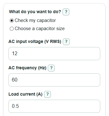
- Choose What do you want to do?: use Check my capacitor if you already picked a Filter capacitor (uF), or Choose a capacitor size if you have an Allowed ripple (V peak-to-peak) limit.
- Enter AC input voltage (V RMS), AC frequency (Hz), and Load current (A). Use the transformer secondary rating, not the wall outlet, unless you are trained for mains work.
- Open Advanced options only if you need to change Drop across one diode (V), Capacitor shortfall to allow (percent), Extra ripple cushion (percent), or Number display.
- Click Calculate, then read Main answer first. Check Lowest output during ripple to see if your circuit still has enough voltage at the low point.
- Sanity-check the output: if Typical ripple is a large part of Estimated DC output, or a Check note appears, use a larger capacitor, lower Load current (A), or a higher AC input voltage (V RMS).
Definitions
AC input voltage (V RMS): The sine-wave AC voltage before the bridge, usually the transformer secondary rating. RMS means the AC value that would heat a resistor like the same DC voltage.
Bridge rectifier: Four diodes arranged so both halves of the AC wave push current through the load in the same direction.
Drop across one diode (V): The voltage lost across one conducting diode. A bridge path uses two conducting diodes at a time.
Filter capacitor (uF): The capacitor after the bridge that charges near the peak voltage and discharges into the load between peaks.
Typical ripple: The estimated peak-to-peak up-and-down voltage swing using the entered or recommended capacitor value.
Worst-case ripple with shortfall: Ripple recalculated after reducing capacitance by Capacitor shortfall to allow (percent).
Minimum diode reverse voltage estimate: The estimated reverse voltage one diode may need to block. Real parts should have safety margin above this value.
Estimated bridge heat loss: The power the two conducting bridge diodes turn into heat.
Common mistakes and quick fixes
Mistake: Using wall power for AC input voltage (V RMS) when the circuit is actually powered by a transformer secondary.
Fix: Enter the transformer secondary voltage in AC input voltage (V RMS), and treat high-voltage work as dangerous.
Mistake: Entering Filter capacitor (uF) in farads or nanofarads instead of microfarads.
Fix: Convert the value first; for example, 0.001 F is 1000 uF for Filter capacitor (uF).
Mistake: Setting Load current (A) to the transformer current rating instead of the current your circuit draws after the bridge.
Fix: Use the expected DC load current in Load current (A), then check Estimated bridge heat loss.
Mistake: Leaving Drop across one diode (V) at 0.7 V for a low-voltage supply that uses Schottky diodes.
Fix: Change Drop across one diode (V) to the diode's expected forward drop at your Load current (A).
Mistake: Ignoring Capacitor shortfall to allow (percent) when choosing an electrolytic capacitor.
Fix: Keep a realistic Capacitor shortfall to allow (percent) so Worst-case ripple with shortfall does not surprise you.
Mistake: Looking only at Estimated DC output and missing Lowest output during ripple.
Fix: Make sure Lowest output during ripple is still high enough for your regulator, motor driver, or other load.
Limitations & Key Assumptions / Boundary Conditions
- This is a first-pass estimate for a single-phase full-wave bridge rectifier with a capacitor-input filter and a steady Load current (A).
- The ripple formula works best when Typical ripple is small compared with Peak output after diode drops. If ripple is large, the simple sawtooth estimate can be poor.
- Transformer regulation, winding resistance, diode temperature, capacitor ESR, capacitor ripple-current rating, wiring resistance, and pulsed charging current are not modeled.
- Minimum diode reverse voltage estimate is not a final part rating. Choose a diode or bridge rectifier with voltage margin for line variation and transients.
- Estimated bridge heat loss uses 2 times Drop across one diode (V) times Load current (A). Real heating depends on package, airflow, waveform, and temperature.
- For mains-voltage entries, the math still runs, but high voltage can injure or kill. Use isolation, fuses, proper rated parts, and qualified help.
- If Estimated DC output or Lowest output during ripple is zero or negative, the input combination is outside the useful range of this simplified capacitor-filter model.
Methodology
How the calculation is made
The calculator starts by converting the entered RMS AC voltage to peak voltage. For a sine wave, the peak is RMS times the square root of 2.
V_ac_peak = V_ac_rms * sqrt(2)
A bridge rectifier conducts through two diodes at a time, so the charged capacitor peak is reduced by two diode drops.
V_peak_out = V_ac_peak - 2 * V_f
A full-wave bridge uses both half-cycles, so the ripple repeats twice per AC cycle.
f_ripple = 2 * f_line
In Check my capacitor mode, the printed capacitance is converted from microfarads to farads, then ripple is estimated from load current, ripple frequency, and capacitance.
C_F = C_uF * 0.000001
V_ripple_pp = I_load / (f_ripple * C_F)
Worst-case ripple uses the same formula after reducing capacitance by Capacitor shortfall to allow (percent).
C_effective = C_F * (1 - cap_shortfall_percent / 100)
V_ripple_worst = I_load / (f_ripple * C_effective)
The estimated average DC output treats the ripple shape as roughly sawtooth, so the average is about one-half ripple below the charged peak. The low point is one full ripple amount below the charged peak.
V_dc_est = V_peak_out - V_ripple_pp / 2
V_low = V_peak_out - V_ripple_pp
In Choose a capacitor size mode, the minimum capacitance is found from the allowed ripple. The printed capacitor value is then increased for shortfall and any extra cushion.
C_min_F = I_load / (f_ripple * target_ripple)
C_printed_F = C_min_F * (1 + extra_cushion_percent / 100) / (1 - cap_shortfall_percent / 100)
C_printed_uF = C_printed_F * 1000000
Ripple percent is calculated only when the estimated DC output is positive.
ripple_percent = (V_ripple_pp / V_dc_est) * 100
Bridge heat loss is estimated from the two conducting diode drops. Diode-loss efficiency compares useful output power with output power plus this bridge heat loss.
P_bridge = 2 * V_f * I_load
P_out = V_dc_est * I_load
efficiency_percent = P_out / (P_out + P_bridge) * 100
The diode reverse-voltage estimate is taken as the AC peak voltage. The Main answer is Estimated DC output in check mode and Needed printed capacitor in choose mode.
PIV_est = V_ac_peak
Mini example
With AC input voltage (V RMS) = 12, AC frequency (Hz) = 60, Load current (A) = 0.5, Filter capacitor (uF) = 1000, Drop across one diode (V) = 0.7, and Capacitor shortfall to allow (percent) = 20, the AC peak is 16.97 V and Peak output after diode drops is 15.57 V.
The ripple frequency is 120 Hz. Typical ripple is 0.5 / (120 * 0.001) = 4.17 V peak-to-peak, so Estimated DC output is 15.57 - 4.17 / 2 = 13.49 V. The 20 percent shortfall makes Worst-case ripple with shortfall about 5.21 V peak-to-peak.