
Estimate rectifier ripple voltage, capacitor size, or max load current for a capacitor-filtered power supply.
Advanced options
Table of contents
How to use our Ripple Voltage Calculator
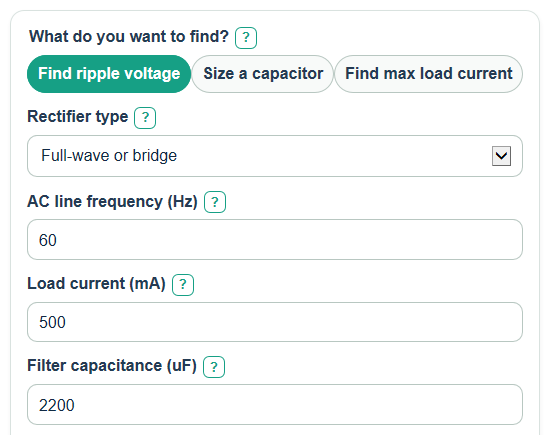
- Pick What do you want to find?: Find ripple voltage, Size a capacitor, or Find max load current.
- Select Rectifier type and enter AC line frequency; use the actual line frequency, such as 60 Hz, because the calculator handles full-wave doubling.
- Enter the visible Load current, Filter capacitance, or Max ripple allowed values needed for your chosen mode.
- Open Advanced options only if you want to allow for Capacitance loss to allow for, enter Approx average DC output, or change Number display.
- After you click Calculate, sanity-check Ripple frequency, Capacitance used in the math, and any Check note before using the Main answer in a design.
Definitions
Peak-to-peak ripple voltage: The voltage difference from the highest point of the ripple to the lowest point, shown as V peak-to-peak.
Ripple frequency: How often the capacitor is recharged each second. Full-wave or bridge rectifiers recharge twice per AC cycle, while half-wave rectifiers recharge once per cycle.
Load current: The DC current your circuit draws from the supply, entered in mA.
Filter capacitance: The capacitor value across the rectifier output, entered in uF. Capacitors in parallel add together.
Capacitance loss: A percent reduction from the label value, used to model tolerance, temperature, aging, or a safety margin.
Estimated RMS ripple: The heating-style value of the AC ripple part, estimated from peak-to-peak ripple with a triangular wave approximation.
Estimated lowest voltage: The approximate low point of the DC output during the ripple swing.
Common mistakes and quick fixes
Mistake: Entering 120 in AC line frequency for a full-wave 60 Hz supply.
Fix: Enter 60 in AC line frequency and choose Full-wave or bridge under Rectifier type.
Mistake: Typing amps into Load current when the label expects mA.
Fix: Convert amps to milliamps first; for example, 0.5 A becomes 500 in Load current.
Mistake: Using farads or nanofarads in Filter capacitance instead of uF.
Fix: Enter the capacitor value in microfarads; for example, 0.0022 F becomes 2200 in Filter capacitance.
Mistake: Leaving Max ripple allowed at a random value when sizing a capacitor or finding max current.
Fix: Set Max ripple allowed to the largest peak-to-peak ripple your circuit can tolerate.
Mistake: Ignoring Capacitance loss to allow for when using electrolytic capacitors with loose tolerance or aging.
Fix: Enter a realistic percent in Capacitance loss to allow for so Capacitance used in the math is lower than the label value.
Mistake: Treating Estimated RMS ripple as an exact oscilloscope reading.
Fix: Use Estimated RMS ripple as a triangular-ripple estimate and check the real waveform if the design is sensitive.
Limitations & Key Assumptions / Boundary Conditions
- The main estimate assumes a capacitor-input rectifier filter with roughly constant DC load current.
- The ripple shape is treated as a simple triangular wave. Real diode conduction pulses, transformer resistance, capacitor ESR, and load changes can shift the measured value.
- The method works best when ripple is small compared with the DC output. If the Check note says the ripple is very large, the real circuit may not follow this simple estimate well.
- Approx average DC output is optional. If you enter it, the calculator estimates the low point as average DC minus half of peak-to-peak ripple.
- Capacitance loss to allow for is a design allowance, not a measured capacitor test. Use the capacitor data sheet or your own margin when accuracy matters.
- The calculator does not check diode voltage drop, transformer regulation, regulator dropout, inrush current, capacitor ripple-current rating, or safety requirements.
Methodology
Core calculation
The calculator first turns the AC line frequency into ripple frequency. A full-wave or bridge rectifier uses two recharge pulses per AC cycle, while a half-wave rectifier uses one. A common rectifier input capacitor estimate relates capacitance, load current, peak-to-peak ripple, and ripple frequency [2].
f_ripple_hz = line_frequency_hz * rectifier_multiplier
rectifier_multiplier = 2 for full_wave; rectifier_multiplier = 1 for half_wave
Next, capacitance is converted from uF to F and reduced by any entered loss percent.
C_eff_F = (capacitance_uf * 1e-6) * (1 - capacitance_loss_pct / 100)
load_current_A = load_current_ma / 1000
Mode formulas
For Find ripple voltage, the calculator solves for peak-to-peak ripple.
Vpp = load_current_A / (f_ripple_hz * C_eff_F)
For Size a capacitor, it solves for the label capacitance needed after allowing for any capacitance loss.
required_capacitance_uf = (load_current_A / (f_ripple_hz * max_ripple_vpp)) * 1e6 / (1 - capacitance_loss_pct / 100)
For Find max load current, it solves for the largest constant load current that still meets the ripple limit.
max_current_ma = max_ripple_vpp * f_ripple_hz * C_eff_F * 1000
Extra outputs
Estimated RMS ripple treats the ripple as a zero-mean triangular wave.
rms_ripple_v = Vpp / (2 * sqrt(3))
If Approx average DC output is entered, the calculator also compares ripple with the average DC level and estimates the low point of the ripple swing.
ripple_percent_of_dc = Vpp / average_dc_voltage_v * 100
estimated_lowest_voltage_v = average_dc_voltage_v - Vpp / 2
Mini-example
For a full-wave 60 Hz supply, 500 mA load, 2200 uF capacitor, and 0% capacitance loss, the ripple frequency is 120 Hz and the effective capacitance is 0.0022 F.
Vpp = 0.5 / (120 * 0.0022) = 1.8939 V peak-to-peak
rms_ripple_v = 1.8939 / (2 * sqrt(3)) = 0.5467 V
With Approx average DC output set to 12 V, the ripple is about 15.78% of the average DC level and the estimated lowest voltage is 11.053 V.