
Choose the circuit type and resistor values to calculate ideal op amp voltage gain and see whether the output signal reverses polarity.
Advanced options
Table of contents
How to use our Op Amp Gain Calculator
- Choose Inverting when the input signal reaches the minus input through Rin. Choose Non-inverting when the input signal reaches the plus input and Rg connects the feedback network to ground or circuit reference.
- Enter Rf and the resistor used by the selected circuit: Rin for an inverting circuit or Rg for a non-inverting circuit. Type values such as 10k, 47k, or 1M.
- Click Calculate. The first result is the signed ideal voltage gain in V/V. A negative sign means the output signal reverses polarity.
- For an ideal output-voltage estimate, open Advanced options and enter Vin. To compare that estimate with a device limit, also enter both minimum and maximum allowed output values from the applicable datasheet conditions.
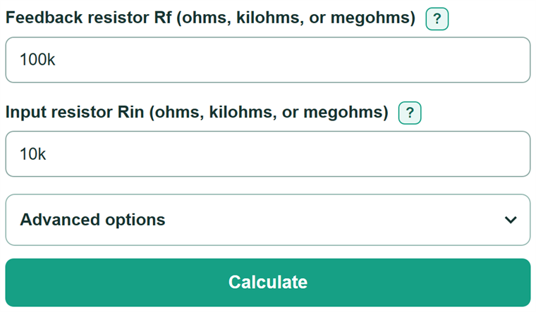
- Sanity-check the resistor ratio. For example, Rf = 100k and Rin = 10k gives -10 V/V, while Rf = 90k and Rg = 10k gives +10 V/V.
Definitions
Closed-loop voltage gain: The ideal output-voltage change divided by the input-voltage change after the feedback resistors are connected. It is written in V/V.
Rf: The feedback resistor from the op amp output to the inverting input.
Rin: In an inverting circuit, the resistor between the input signal and the inverting input.
Rg: In a non-inverting circuit, the resistor from the inverting input to ground or circuit reference.
Signal polarity: Whether an output-voltage change points in the same direction as an input-voltage change. An inverting circuit reverses polarity by 180 degrees.
Decibel (dB): A logarithmic way to state voltage-gain magnitude. The dB value uses absolute gain, so it does not show signal polarity.
Output swing: The usable output-voltage range for a particular op amp under stated supply, load, and temperature conditions.
Common mistakes and quick fixes
Mistake: Using Rin in a non-inverting circuit or Rg in an inverting circuit.
Fix: Use Rin for the resistor from the source to the inverting input. Use Rg for the resistor from the inverting input to ground or circuit reference.
Mistake: Treating a negative gain as an output that is always below zero volts.
Fix: A negative gain reverses polarity. Multiply the signed gain by the signed Vin to get the ideal output voltage.
Mistake: Leaving out the added 1 for a non-inverting circuit.
Fix: Use 1 + Rf/Rg. With nonnegative resistor values, this basic non-inverting circuit has a gain of at least +1 V/V.
Mistake: Typing an unsupported resistor value such as 100kk.
Fix: Enter a number in ohms or use one suffix, such as 1000, 1k, 47k, or 1M. Uppercase M means mega.
Mistake: Entering only one output limit for the range check.
Fix: Enter Vin and both output limits, or leave both output limits blank when you only need gain.
Mistake: Assuming an inside-range result proves the circuit will work.
Fix: Check the selected op amp datasheet for supply voltage, output swing at the actual load, input common-mode range, bandwidth, slew rate, stability, and load current.
Limitations & Key Assumptions / Boundary Conditions
- The equations assume an ideal op amp with negative feedback and a basic resistor-feedback circuit.
- The output-voltage calculation is an ideal DC estimate: signed gain multiplied by signed Vin.
- The output-range check only compares the calculated output with the limits entered. It does not check output swing at the actual load, supply headroom, input common-mode range, bandwidth, slew rate, noise, offset, bias current, stability, or thermal limits.
- Rf, Rin, and Rg must be nonnegative for this passive resistor model. The active denominator resistor, Rin or Rg, must be greater than zero.
- Resistor tolerance, temperature, and real op amp behavior can change measured gain. Use measured resistor values and the selected device datasheet when precision matters.
Methodology
Ideal gain equations
The calculator uses the selected circuit type to choose an ideal closed-loop equation. Av means voltage gain. Rf and the applicable second resistor are converted to the same resistance unit before division.
Av = -Rf / Rin
For an inverting circuit, the minus sign means the ideal output changes in the opposite direction from the input.
Av = 1 + Rf / Rg
For a non-inverting circuit, the added 1 means the ideal gain is +1 V/V when Rf is zero.
Supporting calculations
The dB result uses gain magnitude, so it does not show inversion. If the gain is zero, the calculator displays negative infinity dB instead of a finite number.
Gain (dB) = 20 · log10(|Av|)
When Vin is entered, the calculator estimates the signed ideal output voltage. When both output limits are also entered, it reports whether that estimate is at or between the limits.
Vout = Av · Vin
Worked example
For an inverting circuit with Rf = 100 kOhm and Rin = 10 kOhm, Av = -100/10 = -10 V/V. If Vin = -0.25 V, then Vout = (-10) x (-0.25 V) = +2.5 V. The gain magnitude is 20 dB. Rin and Rg cannot be zero when they are used because division by zero is undefined.