
Calculate an inverting op amp output, gain, missing resistor, dB gain, and a simple supply-rail clipping check.
Table of contents
How to use our Inverting Op Amp Calculator
- Choose What do you want to find?: Ideal output voltage, Needed feedback resistor, or Needed input resistor.
- Enter Input voltage, Input resistor, Feedback resistor, and Wanted gain size only where they apply to your chosen mode.
- Open Advanced options if you want the Supply rail check to use your Positive supply rail, Negative supply rail, and Output headroom from each rail.
- Click Calculate, then check that Signed gain is negative and that Ideal output voltage has the opposite polarity from a positive Input voltage.
- If Supply rail check warns about clipping, use Nearest usable output voltage as a rough limit and redesign the gain, input signal, or supply rails.
Definitions
Inverting op amp: An op amp circuit where the input signal goes through a resistor into the inverting input, so the output flips polarity.
Signed gain: The voltage gain with its polarity sign. In this calculator it is negative for positive resistor values.
Gain size: The positive size of the gain without the inverting minus sign. A gain size of 10 means the signed gain is -10 V/V.
Input resistor: The resistor between the signal source and the inverting input. In the ideal model, it is also the input resistance seen by the source.
Feedback resistor: The resistor from the output back to the inverting input. A larger feedback resistor gives a larger gain size when the input resistor stays the same.
Gain size in dB: A logarithmic way to state voltage gain size. It uses the positive gain size, so the polarity flip is not included.
Supply rail: One of the power-supply voltages that limits how high or low the op amp output can go.
Output headroom from each rail: The voltage gap kept between the ideal output limit and each supply rail.
Bias-balance resistor: An optional resistor at the non-inverting input, often chosen near the parallel value of the input and feedback resistors.
Common mistakes and quick fixes
Mistake: Entering a negative Wanted gain size because the circuit is inverting.
Fix: Enter Wanted gain size as a positive number; Signed gain will include the negative sign.
Mistake: Mixing ohms and kohm in Input resistor or Feedback resistor.
Fix: Enter Input resistor and Feedback resistor in kohm, so 10000 ohms becomes 10 kohm.
Mistake: Treating Ideal output voltage as guaranteed even when the Supply rail check says clipping is likely.
Fix: Compare Ideal output voltage with Nearest usable output voltage before choosing parts.
Mistake: Using a Positive supply rail that is not higher than Negative supply rail.
Fix: Make Positive supply rail higher than Negative supply rail, such as 15 V and -15 V or 5 V and 0 V.
Mistake: Setting Output headroom from each rail larger than the supply range can allow.
Fix: Reduce Output headroom from each rail or use wider rails so there is a usable output range.
Mistake: Forgetting that Input resistance seen by the source is close to Input resistor in the ideal inverting circuit.
Fix: Raise Input resistor if the source cannot drive a low resistance without changing too much.
Limitations & Key Assumptions / Boundary Conditions
- The main gain and output values use the ideal inverting op amp model. Real op amps have input offset voltage, input bias current, finite open-loop gain, and other errors.
- The Supply rail check is a simple range check using Positive supply rail, Negative supply rail, and Output headroom from each rail. It is not an exact saturation model.
- The calculator does not check bandwidth, slew rate, phase margin, noise, distortion, output current limit, or load effects.
- Single-supply inverting amplifiers often need a reference voltage or AC coupling. This calculator treats voltages as entered relative to the circuit reference node.
- The Optional bias-balance resistor is a common design estimate, not a requirement for every op amp. Check the op amp data sheet when bias current matters.
- Resistor tolerance, temperature drift, and standard resistor values can make the built circuit differ from the exact calculated value.
Methodology
Core calculation
The calculator uses the standard ideal inverting amplifier relationship. The feedback resistor and input resistor must be in the same resistance unit, so kohm works directly.
signed_gain = -Rf / Rin
Vout = signed_gain * Vin
The minus sign is the key beginner detail. It means a positive input voltage produces a negative ideal output voltage, and a negative input voltage produces a positive ideal output voltage.
Solving for a missing resistor
When you choose Needed feedback resistor, the calculator uses the positive Wanted gain size and the input resistor.
Rf = gain_size * Rin
When you choose Needed input resistor, it uses the feedback resistor and the positive Wanted gain size.
Rin = Rf / gain_size
After finding the missing resistor, the calculator recalculates the signed gain and ideal output voltage from the completed resistor pair.
Extra outputs
Gain size in dB is based on the absolute value of the signed gain, so the dB result describes size only, not the polarity flip.
gain_db = 20 * log10(abs(signed_gain))
Input resistance seen by the source is the input resistor in the ideal inverting circuit.
input_resistance_kohm = Rin
The optional bias-balance resistor is the parallel value of the input and feedback resistors.
Rb = (Rin * Rf) / (Rin + Rf)
Supply rail check
The usable output range removes the chosen headroom from both supply rails.
usable_low = negative_supply_v + output_headroom_v
usable_high = positive_supply_v - output_headroom_v
If the ideal output is below usable_low, the nearest usable output is usable_low. If the ideal output is above usable_high, the nearest usable output is usable_high. Otherwise, the ideal output is inside the simple usable range.
Mini-example
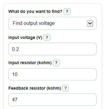
For Vin = 0.2 V, Rin = 10 kohm, and Rf = 47 kohm, the signed gain is -47 / 10 = -4.7 V/V.
Vout = -4.7 * 0.2 = -0.94 V
With rails of +15 V and -15 V and 1 V headroom, the usable range is -14 V to +14 V, so -0.94 V is inside the range.