
Estimate deck light count, total watts, transformer size, and low-voltage wire loss for a simple deck lighting run.
Advanced options
Table of contents
How to use our Deck Lighting Calculator
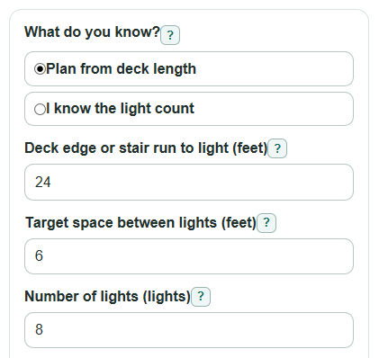
- Choose What do you know?: use Plan from deck length if you want the calculator to count lights from a run length, or I know the light count if you already picked the fixtures.
- Enter Deck edge or stair run to light, Target space between lights, or Number of lights as needed, then enter Power per light from the light package or product specs.
- Open Advanced options if you want to change Extra transformer room, Transformer sizes to check, Low-voltage output, One-way wire length to farthest light, Copper wire size, or How the lights sit on the wire.
- Click Calculate and read Lights to install first, then check Minimum transformer rating and Smallest listed transformer that fits before looking at the wire results.
- Sanity-check the plan: Actual space between lights should look realistic on your deck, Transformer load with suggested size should not exceed your planned reserve, and Estimated wire loss near or above 10 percent deserves a wiring change.
Definitions
Deck edge or stair run to light: The length, in feet, where this group of lights will be placed.
Target space between lights: The spacing you want before the calculator rounds the count to a whole number of lights.
Power per light: The electrical power used by one fixture, measured in watts. This is different from lumens, which describe light output.
Extra transformer room: Spare transformer capacity kept open so the lights are not planned to use the full transformer rating.
Low-voltage output: The voltage supplied by the lighting transformer, commonly selected here as 12 volts or 24 volts.
Copper wire size (AWG): American Wire Gauge. A smaller AWG number means a thicker copper wire and lower resistance.
One-way wire length to farthest light: The distance from the transformer to the farthest light along the wire path, not doubled.
Estimated wire loss: The percent of transformer voltage estimated to be lost in the wire before power reaches the farthest light.
Common mistakes and quick fixes
Mistake: Entering the whole deck perimeter in Deck edge or stair run to light when only one rail section will have lights.
Fix: Use Deck edge or stair run to light for only the rail, edge, or stair run served by this group of lights.
Mistake: Using bulb brightness instead of Power per light.
Fix: Enter Power per light in watts from the package or product specs, not lumens or a color temperature number.
Mistake: Leaving Number of lights at the default after choosing I know the light count.
Fix: Change Number of lights to the actual fixture count for this lighting group.
Mistake: Measuring One-way wire length to farthest light as the out-and-back distance.
Fix: Enter only the one-way path from the transformer to the farthest light; the calculator doubles it for the circuit path.
Mistake: Picking the wrong Copper wire size because smaller AWG sounds smaller.
Fix: For Copper wire size, remember that 12 AWG is thicker than 16 AWG and usually loses less voltage.
Mistake: Removing Extra transformer room by setting it very low without checking Transformer load with suggested size.
Fix: Keep Extra transformer room as a planning buffer unless your light maker gives a different rule, then confirm Transformer load with suggested size is acceptable.
Limitations & Key Assumptions / Boundary Conditions
- This is a planning estimate for one low-voltage deck lighting group, not an electrical code check or a replacement for the light maker's installation manual.
- The light count formula places a light near each end of the entered run in Plan from deck length mode. If you do not want endpoint lights, use I know the light count.
- The wire check assumes copper wire at about room temperature and uses simple AWG resistance values. Real resistance changes with temperature, connections, wire type, and installation details.
- The Spread along the run option uses a simple 0.5 factor for voltage drop. It does not model every tap point or unequal fixture spacing.
- For mixed fixture wattages, the result is only as good as the Power per light value. Calculate each fixture group separately or use a careful weighted average.
- A transformer may have manufacturer rules, maximum run lengths, dimmer limits, or connector limits that are stricter than the wattage estimate.
- The 10 percent Estimated wire loss warning is a practical planning flag for possible dim lights, not a legal limit.
Methodology
How the light count is found
In Plan from deck length mode, the calculator divides the entered run length by the target spacing, rounds up to the next whole spacing interval, and adds one light so there is a light near each end.
light_count = ceil(deck_run_length_ft / target_spacing_ft) + 1
actual_spacing_ft = deck_run_length_ft / (light_count - 1)
In I know the light count mode, the calculator uses Number of lights directly and does not use Deck edge or stair run to light or Target space between lights for the primary count.
How power and transformer size are found
Total light power is the fixture count multiplied by Power per light.
total_power_w = light_count * watts_per_light
The minimum transformer rating keeps the selected Extra transformer room open. For example, 20 percent extra room means the planned light load uses no more than 80 percent of the transformer rating.
minimum_transformer_w = total_power_w / (1 - transformer_reserve_percent / 100)
The suggested transformer is the smallest positive number in Transformer sizes to check that is at least the minimum transformer rating.
suggested_transformer_w = smallest listed size where size >= minimum_transformer_w
transformer_load_percent = 100 * total_power_w / suggested_transformer_w
How the wire check is found
The calculator estimates current from watts and transformer voltage, then estimates voltage drop from current and round-trip wire resistance.
circuit_current_a = total_power_w / supply_voltage_v
wire_resistance_ohm = 2 * one_way_wire_length_ft * (awg_ohms_per_1000_ft / 1000)
voltage_drop_v = circuit_current_a * wire_resistance_ohm * layout_factor
end_voltage_v = supply_voltage_v - voltage_drop_v
voltage_drop_percent = 100 * voltage_drop_v / supply_voltage_v
The layout factor is 0.5 for Spread along the run and 1 for All near the far end. The AWG resistance values used are 6.385, 4.016, 2.525, 1.588, and 0.9989 ohms per 1000 feet for 18, 16, 14, 12, and 10 AWG copper wire.
Worked mini-example
For a 24 foot run with a 6 foot target space, 1.5 watts per light, 20 percent Extra transformer room, 12 volt output, 50 feet of 16 AWG wire, and lights spread along the run, the count is ceil(24 / 6) + 1 = 5 lights.
total_power_w = 5 * 1.5 = 7.5 W
minimum_transformer_w = 7.5 / (1 - 20 / 100) = 9.375 W
circuit_current_a = 7.5 / 12 = 0.625 A
voltage_drop_percent = about 1.05%
With the default transformer list, 30 W is the smallest listed transformer that fits this example.