
Calculate balanced three-phase power, current, voltage, or power factor from line values without mixing up voltage reference or line current.
Table of contents
How to use our Three Phase Power Calculator
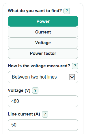
- Choose What do you want to find? so the calculator shows only the values needed for that missing item.
- Set How is the voltage measured? before entering Voltage, because line-to-neutral voltage must be converted before the three-phase formula is used.
- Enter Line current as the current in one wire, enter Power factor from 0 to 1, and enter Real power only when that mode needs it.
- Use Advanced options if you want wye or delta phase values, a leading or lagging Reactive power direction, or a different Number display.
- Sanity-check the result: Real power should not be larger than Apparent power, and Power factor should be closer to 1 for loads that use most supplied power as useful work.
Definitions
Balanced three-phase: A three-phase circuit where the three phase voltages and currents are the same size and spaced evenly in time.
Line-to-line voltage: Voltage measured between two hot lines. This is the voltage used directly in the standard line-value three-phase formula.
Line-to-neutral voltage: Voltage measured from one hot line to neutral. In a balanced wye system, line-to-line voltage is sqrt(3) times this value.
Line current: Current in one line conductor. It is not the three line currents added together.
Real power: Useful power in kW. It is the part of the electrical power that does work, such as turning a motor shaft or making heat.
Apparent power: Total volt-amp load in kVA that wires, transformers, and generators must carry.
Reactive power: Power in kVAR that moves back and forth because voltage and current are not perfectly lined up.
Power factor: Real power divided by apparent power. It is a number from 0 to 1, where 1 means all apparent power is real power.
Phase angle: The angle in degrees between voltage and current, found from the power factor.
Wye and delta: Common three-phase connection types. They change phase voltage and phase current relationships, but not total balanced three-phase power when line voltage and line current are already known.
Common mistakes and quick fixes
Mistake: Using Voltage as line-to-neutral while How is the voltage measured? is set to between two hot lines.
Fix: Change How is the voltage measured? to from hot line to neutral, or enter the true line-to-line Voltage.
Mistake: Adding all three wires and typing the total into Line current.
Fix: Enter the current in one line conductor only; the calculator already includes the three-phase factor.
Mistake: Typing 85 into Power factor when you mean 0.85.
Fix: Enter Power factor as a decimal from 0 to 1, such as 0.85.
Mistake: Entering Apparent power or kVA in Real power.
Fix: Use Real power only for useful power in kW; the calculator computes Apparent power separately.
Mistake: Choosing Show phase values for delta and treating a line-to-neutral Voltage as a delta winding voltage.
Fix: Use the Check note and Line-to-line voltage result; delta Phase voltage equals line-to-line voltage.
Mistake: Picking the wrong Reactive power direction and getting the wrong sign on Reactive power.
Fix: Use lagging for motor-style inductive loads and leading for capacitor-style loads.
Limitations & Key Assumptions / Boundary Conditions
- This calculator assumes a balanced three-phase AC load. It does not model unbalanced phase currents, neutral current, harmonics, or waveform distortion.
- Use RMS AC values for Voltage and Line current. Peak values or meter readings from a different reference point will give wrong results.
- Power factor is treated as a single number from 0 to 1. It does not separate displacement power factor from distortion power factor.
- When solving for Power factor, Real power cannot be larger than Apparent power. If it is, the input set is physically inconsistent for this model.
- Wye and delta settings only affect Phase voltage and Phase current outputs. They do not change Real power, Apparent power, or Reactive power when line values are known.
- Reactive power sign follows the selected Reactive power direction: lagging is positive and leading is negative in this calculator.
- Real equipment may need extra margin for starting current, service factor, efficiency, voltage drop, code rules, and manufacturer ratings.
Methodology
Core line-value method
The calculator first converts the entered Voltage to line-to-line voltage, then applies balanced three-phase power formulas. The real power formula using line-to-line voltage, line current, and power factor is the standard balanced three-phase form [1].
If voltage is line-to-line: V_LL = V_input
If voltage is line-to-neutral: V_LL = sqrt(3) * V_input
S_kVA = sqrt(3) * V_LL * I_L / 1000
P_kW = S_kVA * PF
Here, V_LL is line-to-line voltage in volts, I_L is line current in amps, S_kVA is apparent power, P_kW is real power, and PF is power factor. Apparent power uses kVA, real power uses kW, and reactive power uses kVAR [2].
Solving for the missing value
For Power mode, the calculator uses the entered Voltage, Line current, and Power factor to find Real power. For Current mode, it rearranges the same formula:
I_L = P_kW * 1000 / (sqrt(3) * V_LL * PF)
For Voltage mode, it solves for line-to-line voltage:
V_LL = P_kW * 1000 / (sqrt(3) * I_L * PF)
If How is the voltage measured? is set to line-to-neutral in Voltage mode, the primary voltage answer is:
V_LN = V_LL / sqrt(3)
For Power factor mode, it divides real power by apparent power:
PF = P_kW / S_kVA
If this result is above 1, the calculator shows an error instead of forcing the value down to 1.
Reactive power and angle
Reactive power and phase angle are based on the power triangle relationship between real, reactive, and apparent power [2].
Q_kVAR = direction_sign * S_kVA * sqrt(1 - PF^2)
angle_deg = acos(PF) * 180 / pi
The direction_sign is +1 for lagging and -1 for leading, so leading reactive power is shown as a negative kVAR value.
Optional phase values
When Show phase values for is set to wye or delta, the calculator adds phase voltage and phase current using standard line-to-phase relationships [3].
Wye: V_phase = V_LL / sqrt(3); I_phase = I_L
Delta: V_phase = V_LL; I_phase = I_L / sqrt(3)
These phase values are supporting details. They do not change the total balanced three-phase power result.
Worked mini-example
With 480 V measured between two hot lines, 50 A line current, and a power factor of 0.85, apparent power is:
S_kVA = sqrt(3) * 480 * 50 / 1000 = 41.57 kVA
Real power is:
P_kW = 41.57 * 0.85 = 35.33 kW
For a lagging load, reactive power is about 21.90 kVAR and the phase angle is about 31.79 degrees.