
Find power factor, kVA, kVAR, phase angle, and correction kVAR from nameplate, meter, or bill values.
Advanced options
Table of contents
How to use our Power Factor Calculator
- Choose What do you want to find? based on the numbers you already have, such as Real power (kW) and Apparent power (kVA).
- Enter only the visible required fields for that mode, then pick Circuit type when Voltage (V) and Current (A) are part of the calculation.
- Open Advanced options if you need Load behavior, capacitor settings, or a different Number style; leave the defaults if you only need the basic power triangle.
- Click Calculate and read Main answer first, then use Power factor, Apparent power, Reactive power, and Phase angle to understand the load.
- Sanity-check the result: Power factor should be between 0 and 1, and Apparent power (kVA) should not be smaller than the absolute Real power (kW).
Definitions
Real power (kW): The part of AC power that does useful work, such as turning a motor, heating a coil, or lighting a lamp.
Apparent power (kVA): The total electrical load carried by the supply wires and transformer. It combines real power and reactive power.
Reactive power (kVAR): Power that moves back and forth in AC equipment such as motors, coils, transformers, and capacitors. Lagging reactive power is shown as positive by default, and leading reactive power is shown as negative.
Power factor: Real power divided by apparent power. In the simple sine-wave model, it is also the cosine of the phase angle between voltage and current [1].
Phase angle: The angle between voltage and current. A larger phase angle gives a lower power factor.
RMS: The effective AC value used for voltage and current ratings. Enter RMS values for Voltage (V) and Current (A).
Correction needed (kVAR): The reactive power a capacitor bank would supply to move from Current power factor to Target power factor.
Microfarads: A unit of capacitance. The Capacitor size estimate reports microfarads per section when the needed capacitor data is usable.
Common mistakes and quick fixes
Mistake: Entering watts in Real power (kW).
Fix: Convert watts to kilowatts first, so 100,000 W becomes 100 in Real power (kW).
Mistake: Using Apparent power (kVA) that is smaller than Real power (kW).
Fix: Recheck the meter or nameplate, because Apparent power (kVA) must be at least as large as the absolute Real power (kW).
Mistake: Typing 80 instead of 0.80 in Current power factor or Target power factor.
Fix: Enter power factor as a decimal from 0 to 1, such as 0.80 or 0.95.
Mistake: Choosing the wrong Circuit type for Voltage (V) and Current (A).
Fix: Use Single-phase for a single-phase load and Three-phase only for a balanced three-phase system.
Mistake: Ignoring Load behavior when Reactive power (kVAR) is leading.
Fix: Select Leading, like a capacitor-heavy load, so Reactive power (kVAR) keeps the correct negative sign.
Mistake: Treating Capacitor size estimate as a ready-to-buy part number.
Fix: Use Capacitor size estimate only as a math estimate, then choose rated equipment that matches voltage, duty, harmonics, switching, and code requirements.
Limitations & Key Assumptions / Boundary Conditions
- The formulas use the basic sinusoidal AC power triangle. Harmonics, distorted waveforms, unbalanced three-phase loads, and changing motor load can make field readings differ.
- Three-phase Voltage (V) and Current (A) calculations assume a balanced system and line-to-line voltage.
- Correction needed (kVAR) is a sizing estimate, not a final equipment selection. Real capacitor banks need rated voltage, duty rating, discharge method, switching plan, fusing, and harmonic checks.
- If Target power factor is lower than Current power factor, the calculator keeps a negative correction result instead of forcing it to zero.
- Capacitor size estimate depends strongly on Capacitor voltage used for microfarads (V), Frequency (Hz), and Capacitor connection. Wrong settings can change the microfarad result a lot.
- Power factor values must be from 0 to 1. A calculated value above 1 usually means the kW, voltage, current, or phase entry does not describe the same load condition.
Methodology
Power triangle calculations
The calculator treats real power as P in kW, apparent power as S in kVA, reactive power as Q in kVAR, and power factor as PF. Matching kilo units are used, so kW, kVA, and kVAR fit the same power triangle.
PF = P / S
S = P / PF
Q = sign * sqrt(S^2 - P^2)
Q = sign * P * tan(acos(PF))
PF = abs(P) / sqrt(P^2 + Q^2)
The sign is +1 for lagging load behavior and -1 for leading load behavior. Power factor itself is reported as a magnitude from 0 to 1, while Reactive power (kVAR) keeps its sign.
Voltage and current mode
When Voltage (V) and Current (A) are used, the calculator first finds apparent power, then compares Real power (kW) with that apparent power.
single-phase: S_kVA = V * I / 1000
balanced three-phase: S_kVA = sqrt(3) * V_LL * I / 1000
For a balanced three-phase system, sqrt(3) is 1.7320508075688772. The same apparent power can also be turned back into line current when correction results include before and after current.
single-phase: I = S_kVA * 1000 / V
balanced three-phase: I = S_kVA * 1000 / (sqrt(3) * V_LL)
Correction and capacitor estimate
For correction mode, the calculator compares the tangent of the present power factor angle with the tangent of the target power factor angle. This is the standard kVAR correction method for moving from one power factor to another [2].
Qc = sign * P * (tan(acos(PF_current)) - tan(acos(PF_target)))
If Qc is positive for a lagging load, capacitive correction is needed. If Qc is zero, the current and target power factors match. If Qc is negative, the target is lower than the current state or the load direction does not match the usual lagging correction case.
For capacitance, the calculator converts kVAR to VAR by multiplying by 1000, then converts farads to microfarads by multiplying by 1,000,000.
single capacitor: C_F = Qc_VAR / (2 * pi * f * V^2)
three-phase capacitor bank: C_F_each = Qc_VAR / (3 * 2 * pi * f * V^2)
Mini-example
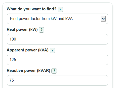
Suppose Real power (kW) is 100 and Apparent power (kVA) is 125. Power factor is 100 / 125 = 0.80. Reactive power is sqrt(125^2 - 100^2) = 75 kVAR for a lagging load, and the phase angle is about 36.87 degrees.
If the same 100 kW load is corrected from Current power factor 0.80 to Target power factor 0.95, Correction needed is about 42.13 kVAR. On a 480 V balanced three-phase system, Apparent power after correction is 100 / 0.95 = 105.26 kVA, current drops from about 150.35 A to 126.61 A, and a 60 Hz three-phase capacitor bank estimate is about 161.68 microfarads per section.
Validation checks
The calculator rejects blank visible required numbers, power factor values outside 0 to 1, division by zero, nonpositive voltage or current, and any kW and kVA combination where Apparent power (kVA) is smaller than the absolute Real power (kW). If rounding makes a square-root term slightly negative, it is treated as zero; larger impossible values show an error.