
Calculate fiber-only one-way delay and round-trip time from a known route length or a map-based route estimate.
Table of contents
How to use our Fiber Propagation Delay and Network Latency Calculator
- Choose Known route length if you have a carrier quote, survey, or cable record; otherwise choose Map distance estimate.
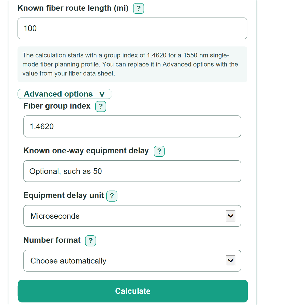
- For a known route, enter Known fiber route length (mi). You can also type a value with mi, km, m, or ft after it.
- For a map estimate, enter Map distance (mi), then set Route factor and Added slack and service loops (mi) only for length not already included.
- Open Advanced options only if needed. Keep the default Fiber group index for the planning profile, or replace it from the exact fiber data sheet and wavelength. Add Known one-way equipment delay only when you know the aggregate one-way value.
- Check Calculated optical path length first. Then use One-way fiber propagation delay and Fiber-only round-trip delay as propagation floors, not as a guaranteed ping time.
Definitions
Optical path length: The length the light signal travels in fiber. For a map estimate, it is map distance times route factor, plus added slack.
Route factor: A multiplier for detours between map distance and the likely installed route. A factor of 1.15 means a route estimated to be 15% longer than the map distance.
Fiber group index: A unitless number used to model the signal's group velocity in fiber. A larger value means slower propagation and more delay. The default 1.4620 is a 1550 nm single-mode planning profile.
One-way fiber propagation delay: The physical travel time in one direction through the calculated optical path. It excludes device processing, queueing, routing, and serialization.
Fiber-only round-trip delay: Twice the one-way fiber propagation delay, assuming the return path has the same length and group index.
Known one-way equipment delay: An optional aggregate delay from equipment or processing in one direction. It is added after the fiber-only calculation.
Common mistakes and quick fixes
Mistake: Entering a straight-line map measurement as Known fiber route length (mi).
Fix: Choose Map distance estimate and enter the measurement in Map distance (mi), then add a Route factor.
Mistake: Applying Route factor or Added slack and service loops (mi) to a surveyed cable route.
Fix: Choose Known route length and enter the complete documented route only. Map adjustments do not apply in that mode.
Mistake: Treating One-way fiber propagation delay as ping time.
Fix: Use Fiber-only round-trip delay for the out-and-back propagation floor, then allow for network delays that are not modeled.
Mistake: Entering a device RTT in Known one-way equipment delay.
Fix: Enter only the aggregate one-way equipment delay. Leave the field blank if the specification does not state its direction.
Mistake: Reusing a group index from a different fiber type or wavelength.
Fix: Check the exact fiber data sheet and operating wavelength, then replace Fiber group index if a more appropriate effective group index is available.
Limitations & Key Assumptions / Boundary Conditions
- The fiber-only results are theoretical propagation floors, not predictions of ping, application response time, or a service-level guarantee.
- The calculation assumes the return path has the same optical length, fiber group index, and entered equipment delay as the forward path.
- Queueing, packet serialization, routing decisions, signal regeneration, forwarding behavior, and unknown device delays are excluded.
- Map mode is only as accurate as the map distance, Route factor, and Added slack and service loops (mi). A known route length should be used when available.
- The default Fiber group index is a planning value for a specific single-mode profile at 1550 nm. Actual delay can differ with fiber type, wavelength, and the value in the applicable data sheet.
- Known one-way equipment delay must be an aggregate one-way value. Do not use a round-trip device specification without converting it appropriately.
Methodology
Calculation method
The calculator first converts each accepted distance entry to meters. A bare distance is miles because the visible distance labels use miles; mi, km, m, and ft suffixes can be entered directly. In Known route length mode, the entered route is the full optical path. In Map distance estimate mode, the route factor and slack create the optical path.
optical path (m) = known route length (m)
optical path (m) = map distance (m) x route factor + added slack (m)
One-way propagation delay uses the fiber group index and the exact vacuum speed of light, 299,792,458 m/s.
one-way fiber delay (ms) = optical path (m) x group index / 299792458 x 1000
fiber-only RTT (ms) = 2 x one-way fiber delay (ms)
If a Known one-way equipment delay is entered, it is converted from ns, us, or ms to milliseconds and added once to the one-way delay. The equipment-inclusive RTT doubles that combined one-way estimate.
estimated one-way latency (ms) = one-way fiber delay (ms) + equipment delay (ms)
estimated RTT (ms) = 2 x estimated one-way latency (ms)
Worked example
With a 100 mi known fiber route and a group index of 1.4620, the optical path is 100 mi. The one-way fiber propagation delay is about 0.7848 ms, and the fiber-only round-trip delay is about 1.5697 ms. If known one-way equipment delay is 50 us, or 0.0500 ms, the estimated one-way latency becomes about 0.8348 ms and estimated RTT becomes about 1.6697 ms.
Assumptions and limits
The group index models group velocity, which is the relevant speed for a signal envelope traveling through fiber. The route factor must be at least 1 because it models an installed path that is equal to or longer than a map measurement. The result excludes traffic-dependent queueing and other delays unless a known aggregate one-way equipment delay is entered.