
Enter project current-demand and anode data to calculate protective current, anode mass, and how long the installed mass may last.
Table of contents
How to use our Cathodic Protection Anode Mass Calculator
- Enter the Area needing protection from the surface-area schedule, drawing, or field measurement.
- Enter the project Design current density in mA/m2 and the Target design life in years from the approved design basis.
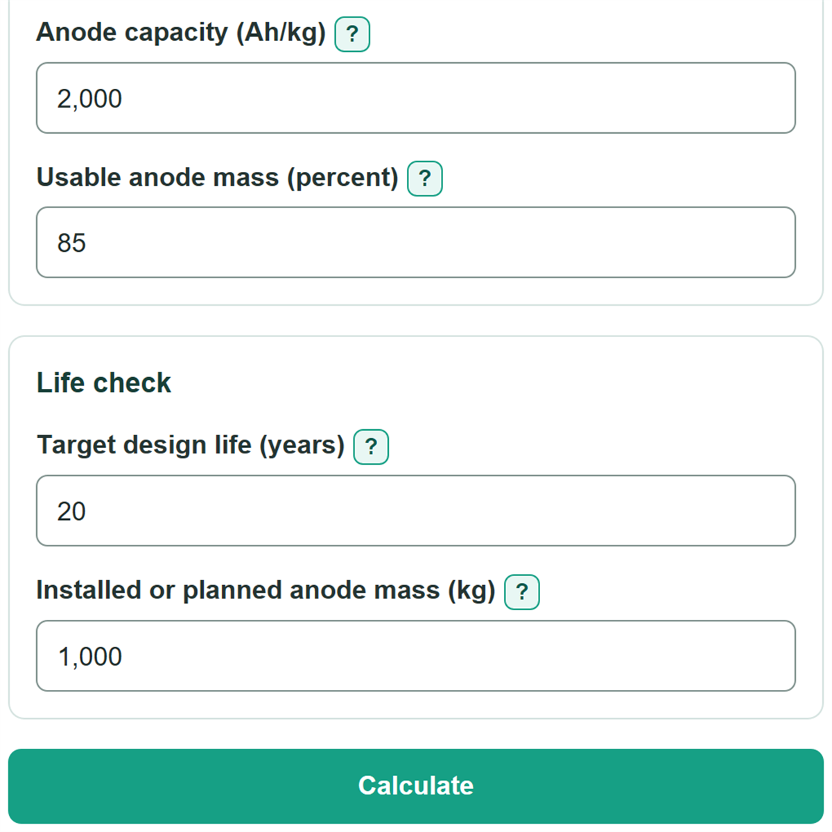
- Copy the exact material's Anode capacity and Usable anode mass percentage from the supplier data or project specification.
- Enter the net active material in Installed or planned anode mass, then select Calculate.
- Check that Target design life covered is at least 100 percent and that Installed anode mass gap is not negative; then confirm the inputs against the project design calculation.
Definitions
Cathodic protection: A corrosion-control method that supplies protective electric current to a metal structure.
Design current density: The protective current assigned to each square meter of protected surface, entered here in mA/m2.
Anode capacity: The electric charge an anode material can deliver per kilogram, entered in ampere-hours per kilogram (Ah/kg).
Usable anode mass: The percentage of installed active anode material expected to be used before replacement.
Installed anode mass gap: Installed or planned active anode mass minus the calculated mass required for the target life. A negative value means more mass is needed.
Target design life covered: Estimated installed-anode life divided by the target design life, shown as a percent.
Common mistakes and quick fixes
Mistake: Entering current density in A/m2 when Design current density is labeled mA/m2.
Fix: Convert amperes per square meter to milliamperes per square meter before entering it. For example, 0.01 A/m2 is 10 mA/m2.
Mistake: Using the whole structure size instead of the surface included in Area needing protection.
Fix: Use only the submerged or buried area covered by the cathodic protection design basis.
Mistake: Entering an anode current rating as Anode capacity.
Fix: Enter electrochemical capacity in Ah/kg from the material data sheet, not a current value in A.
Mistake: Typing 0.85 for Usable anode mass when the label asks for percent.
Fix: Enter 85 for 85 percent. The calculator converts the percentage to a fraction internally.
Mistake: Including cores, cables, or mounting hardware in Installed or planned anode mass.
Fix: Use the net mass of active anode material only.
Mistake: Reading a negative Installed anode mass gap as zero extra mass needed.
Fix: A negative gap is the additional active anode mass needed to reach the selected target life under the entered assumptions.
Limitations & Key Assumptions / Boundary Conditions
- The calculation assumes protective current demand stays constant for the full design life.
- It uses 8,760 hours per year, based on 365 days, and does not adjust for leap years.
- Current distribution, anode resistance, coating deterioration, temperature, salinity, soil conditions, and interference are not modeled.
- Anode capacity and usable mass must be project-specific values for the exact material and operating conditions.
- The result sizes active anode material from the entered values. It does not include separate construction allowances, electrical continuity checks, monitoring criteria, or compliance review.
- Zero or negative area, current density, design life, capacity, or installed mass cannot produce a useful sizing result. Usable anode mass must be more than 0 and no more than 100 percent.
Methodology
Calculation method
The calculator first converts current density from milliamperes to amperes and multiplies it by the protected area. This area-times-current-density approach is used in cathodic protection current calculations. [1]
I = A x i / 1000
In this formula, I is required protective current in A, A is area needing protection in m2, and i is design current density in mA/m2.
Usable anode mass is converted from a percent to a decimal fraction.
u = p / 100
In this formula, u is the usable fraction and p is usable anode mass in percent.
The required active anode mass is the current needed over the design life, divided by usable charge capacity per kilogram.
Mrequired = I x 8760 x Y / (C x u)
The installed-mass life uses the same charge balance in reverse.
Yinstalled = Minstalled x C x u / (I x 8760)
The signed mass gap and life coverage compare the installed mass with the selected target.
Mgap = Minstalled - Mrequired
Coverage = Yinstalled / Y x 100
Worked example
With 1,000 m2, 10 mA/m2, a 20-year target, 2,000 Ah/kg capacity, 85 percent usable mass, and 1,000 kg installed, required current is 10 A. Required mass is about 1,030.59 kg. Estimated installed-mass life is about 19.41 years, so coverage is about 97.03 percent and the mass gap is about -30.59 kg.
Calculation boundaries
The method is a constant-demand charge-balance estimate. It does not predict changing current demand, anode output, or current distribution in a real structure. Use project design criteria and applicable engineering review before selecting an anode system.