
Enter the known anodizing values to calculate time, oxide thickness, or current density and the rectifier amps needed for the exposed load area.
Table of contents
How to use our Anodizing Current Density, Time and Oxide Thickness Calculator
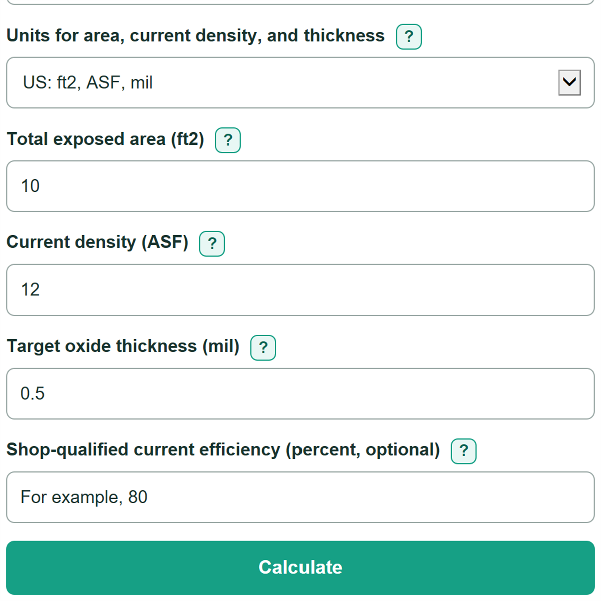
- Choose the missing value under "What do you want to find?" and select the unit system that matches your drawing or process instruction.
- Enter "Total exposed area" for all anodized surfaces in the load, including unmasked inside and back surfaces.
- Enter the two visible process values, using "Time at full current" only after the load has reached full current.
- For a time calculation, optionally enter "Shop-qualified current efficiency (percent, optional)" only if your shop has established that value from its own process records.
- Click Calculate, then sanity-check that "Required rectifier current" equals the active current density times the total exposed area and that the time is practical for your qualified process.
Definitions
Current density (ASF or A/dm2): Electrical current spread over anodized area. ASF means amps per square foot; A/dm2 means amps per square decimeter.
Total exposed area: The combined area of every surface in the load that receives anodizing.
Oxide thickness (mil or um): The thickness of the anodic oxide coating. A mil is 0.001 inch, and 1 mil equals 25.4 um.
Time at full current: The minutes after the load has reached the intended current, excluding any current ramp.
Current efficiency: A shop-qualified percentage used to adjust nominal time when actual oxide growth is less than the nominal model assumes.
Rectifier current: The total amps needed for the load, found by multiplying exposed area by current density.
Common mistakes and quick fixes
Mistake: Entering total rectifier amps in "Current density."
Fix: Enter the process instruction's ASF or A/dm2 value in "Current density"; use "Required rectifier current" for total amps.
Mistake: Counting only the front face in "Total exposed area."
Fix: Include every surface that will anodize across all parts, except surfaces actually masked or held by rack contact.
Mistake: Entering a mil value while metric units are selected, or a um value while US units are selected.
Fix: Match "Units for area, current density, and thickness" to the source document before entering "Target oxide thickness."
Mistake: Including ramp-up in "Time at full current."
Fix: Enter only the dwell time after the load reaches full current; this nominal calculation does not model ramp time.
Mistake: Treating "Nominal 720-rule time" as a guaranteed production time.
Fix: If your shop has a qualified value, enter "Shop-qualified current efficiency (percent, optional)" and use "Qualified planning time" as a scheduling comparison.
Limitations & Key Assumptions / Boundary Conditions
- The calculation uses the nominal 720-rule relationship: 720 amp-minutes per square foot per mil. It is a planning method, not a production specification.
- It assumes full-current dwell time. Current ramp, voltage behavior, and rack contact are not modeled.
- Actual oxide growth can differ with alloy, bath chemistry, temperature, agitation, racking, dissolution, and shop process conditions.
- The optional efficiency adjustment is only as reliable as the shop-qualified efficiency entered. Leave it blank if no qualified value is available.
- Required rectifier current is the calculated load current. Confirm rectifier capacity, voltage limits, lead capacity, and process limits separately.
- Area must include all anodized surfaces in the load. Missing surfaces will understate required rectifier current.
Methodology
Nominal 720-rule calculation
The calculator normalizes US and metric entries, then uses the nominal 720-rule relationship for aluminum anodizing planning. The rule uses 720 amp-minutes per square foot for each mil of oxide thickness. [1]
nominal time (minutes) = 720 x thickness (mil) / current density (ASF)
For thickness mode, the relationship is rearranged.
calculated thickness (mil) = current density (ASF) x time at full current (minutes) / 720
For current-density mode, it is rearranged again.
required current density (ASF) = 720 x target thickness (mil) / time at full current (minutes)
Load current is calculated separately from the active current density and total exposed area.
required rectifier current (amps) = exposed area (ft2) x active current density (ASF)
Unit handling and efficiency
Metric entries are converted before calculation: 1 ft2 equals 9.290304 dm2, and 1 mil equals 25.4 um. A supplied shop-qualified efficiency changes only the time planning comparison.
qualified planning time (minutes) = nominal time / (efficiency percent / 100)
Added time is qualified planning time minus nominal time.
Worked example
For 12 ft2 of exposed area, 12 ASF, and a 0.5 mil target, nominal time is 720 x 0.5 / 12 = 30 minutes. Required rectifier current is 12 x 12 = 144 amps. With a qualified efficiency of 80%, planning time is 30 / 0.80 = 37.5 minutes, or 7.5 added minutes.
Calculation boundaries
All visible required values must be greater than zero. The calculator does not estimate ramp contribution, bath condition, alloy response, or rectifier voltage. It uses only full-current dwell time and the entered total exposed area.