
Calculate screw conveyor capacity or required RPM, then estimate preliminary shaft power, torque, and motor size from your dimensions and material data.
Advanced options
Calculation details
Table of contents
How to use our Screw Conveyor Capacity, Speed and Motor Power Calculator
- Choose What do you want to find?: use Calculate capacity when you know screw RPM, or Find required RPM when you know the needed material rate.
- Choose How material enters the screw, then enter the screw outside diameter, center shaft outside diameter, flight pitch, trough loading, and bulk density from drawings and material records.
- Enter either Known screw speed or Required material rate, and choose the matching Required material rate unit.
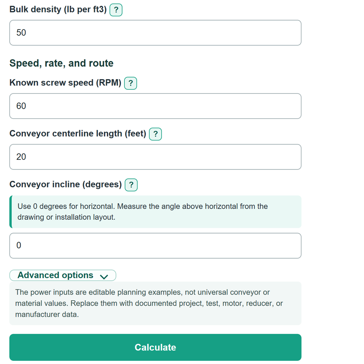
- Enter the conveyor centerline length and conveyor incline. Open Advanced options to replace the example capacity adjustment, resistance, empty-running power, drive efficiency, and motor sizing allowance.
- Click Calculate and sanity-check that CFH, lb/hr, and short tons/hr agree with the entered bulk density. For a horizontal conveyor, calculated vertical lift and estimated vertical lift power should both be zero.
Definitions
CFH: Cubic feet per hour, a loose material volume flow rate.
Bulk density: Loose material weight per cubic foot. It converts CFH into lb/hr and short tons/hr.
Trough loading: The percent of the screw's geometric volume occupied by material. It is entered as a percent, such as 30.
Flight pitch: The distance along the shaft from one flight to the matching point on the next flight.
Capacity adjustment: A documented percent correction applied to geometric capacity for actual conveyor or material behavior.
Vertical lift: The discharge height above the inlet calculated from conveyor centerline length and incline.
Empty-running power: Shaft power for rotating parts, bearings, and seals before material load is added.
Drive efficiency: The share of input power delivered through the drive. A lower percentage requires more motor power for the same shaft load.
Motor sizing allowance: A multiplier applied after drive efficiency to provide the selected design margin before rounding up to a listed motor size.
Common mistakes and quick fixes
Mistake: Entering 0.30 for Trough loading when the field expects a percent.
Fix: Enter 30 for 30 percent. The calculator rejects values that are not above 0 and no more than 100 percent.
Mistake: Using motor RPM for Known screw speed .
Fix: Enter screw-shaft RPM after the reducer, from a tachometer, VFD record, or reducer ratio.
Mistake: Mixing a mass rate with the wrong Required material rate unit .
Fix: Match the selector to the process document. Short tons/hr uses 2,000 lb per short ton, while CFH is a volume rate.
Mistake: Entering the flight-root diameter instead of Screw outside diameter .
Fix: Measure across the outside edges of the flights, then enter the center pipe or shaft separately as Center shaft outside diameter .
Mistake: Treating the default Drive efficiency and Motor sizing allowance as equipment ratings.
Fix: Replace the examples with documented motor, reducer, coupling, and project values before using the motor result for planning.
Mistake: Treating a flood-fed inlet as an ordinary conveyor condition.
Fix: Choose the correct How material enters the screw setting and have flood-fed feeder inlet and flight design reviewed separately.
Limitations & Key Assumptions / Boundary Conditions
- This is a preliminary control-fed screw conveyor estimate. Flood-fed screw feeders need separate inlet, flight, and feeder-design review.[1]
- The geometric capacity model assumes the entered screw diameter, shaft diameter, pitch, trough loading, and capacity adjustment describe the installed conveyor. Short, cut, ribbon, tapered, or other modified flights may need a different method.
- Bulk density, trough loading, and resistance can change with moisture, particle size, aeration, temperature, compaction, and material condition. Use project or test values rather than treating the examples as material facts.[2]
- Horizontal material power uses the entered resistance assumption, and lift power is an ideal mechanical lifting estimate. The result is not an official manufacturer horsepower rating.
- The motor recommendation rounds a calculated planning requirement to a common listed size. Final selection must check starting and upset torque, motor duty, reducer and shaft ratings, bearings, controls, overload protection, and guarding.
- The incline model accepts 0 through 90 degrees and calculates lift from straight centerline length and angle. It does not model curved routes or multiple conveyor sections.
Methodology
Capacity calculation
The calculator finds the open area inside the flights by subtracting the center shaft area from the screw area. It then multiplies that area by pitch, trough loading, and capacity adjustment to find adjusted volume per revolution.
A = (π/4) x (D^2 - d^2) / 144
V = A x (P/12) x (L/100) x (C/100)
Q = V x RPM x 60
In these equations, A is open area in square feet, D is screw outside diameter in inches, d is center shaft outside diameter in inches, V is adjusted volume per revolution in cubic feet, P is flight pitch in inches, L is trough loading in percent, C is capacity adjustment in percent, and Q is capacity in CFH.
For Find required RPM, the calculator first converts the requested rate to CFH. A lb/hr target is divided by bulk density, and a short tons/hr target is multiplied by 2,000 then divided by bulk density.
RPM = target CFH / (V x 60)
Power and torque calculation
Mass rate equals CFH times bulk density. Vertical lift equals conveyor centerline length times the sine of the incline angle. The simplified power estimate adds empty-running power, horizontal material power, and lift power.
Horizontal HP = (lb/hr x length x resistance/100) / 1,980,000
Lift HP = (lb/hr x vertical lift) / 1,980,000
Shaft HP = empty-running HP + horizontal HP + lift HP
Motor requirement = shaft HP x motor sizing allowance / (drive efficiency/100)
The calculator rounds that requirement up to the next value in its planning list. Running screw-shaft torque uses shaft horsepower and operating screw RPM.
Torque (lb-ft) = shaft HP x 33,000 / (2 x π x RPM)
Worked example
With a 12-inch screw, 3-inch center shaft, 12-inch pitch, 30 percent trough loading, 100 percent capacity adjustment, and 60 RPM, the calculated capacity is about 795.2 CFH. At 50 lb/ft3, that is about 39,760.8 lb/hr or 19.88 short tons/hr. With a 20-foot horizontal route, 10 lbf per 100 lb resistance, 0.5 HP empty-running power, 90 percent drive efficiency, and a 1.25 motor sizing allowance, shaft power is about 0.540 HP and the calculated motor requirement is about 0.750 HP, which rounds to a 1 HP planning size.
Calculation scope
The power equations are transparent simplified estimates using your entered resistance and drive assumptions. A zero-degree incline produces exactly zero vertical lift and lift power. The calculator blocks impossible geometry, invalid percentages, and drive efficiency at or below zero so it does not produce a misleading result.