
Estimate pneumatic cylinder free-air demand in SCFM for compressor planning, including separate peak flow and duty-adjusted average air use.
Machine operation
Cylinder counts and active time
Advanced options
Line and valve volumes
Planning assumptions
Calculation details
Table of contents
How to use our Pneumatic Cylinder Air Consumption and Compressor Size Calculator
- Choose Cylinder type. Select double acting when supply air powers both extension and retraction.
- Copy Cylinder bore, Piston rod diameter when shown, and Stroke length from the cylinder catalog or drawing. Fractional inches such as 1 1/8 are accepted.
- Enter Regulated pressure at the cylinder from the nearby regulator gauge and enter Complete cycles per minute. One complete cycle is one extension plus one retraction.
- Enter Identical cylinders installed, the largest number of Cylinders moving at the same time, and Active time during the planning period. Add line volumes or extra compressor capacity only if you know them.
- Click Calculate. Compare Compressor flow to plan for with compressor capacity at the required pressure, and make sure it is at least as large as Peak simultaneous cylinder demand.
Definitions
SCFM: Standard cubic feet per minute. This is free-air flow expressed at a reference condition, so it can be compared with compressor flow ratings.
psig: Pounds per square inch measured above local atmospheric pressure, like a typical regulator gauge reading.
psia: Pounds per square inch absolute, measured from a perfect vacuum. The calculator adds psig to local atmospheric pressure before making the pressure ratio.
Complete cycle: One extension plus one retraction. A single-acting cylinder includes only its powered air stroke.
Peak simultaneous cylinder demand: SCFM for the entered number of identical cylinders that can cycle at the same time.
Duty-adjusted average air use: SCFM for all installed identical cylinders after the active-time percentage is applied.
Annular area: The retract-side piston area of a double-acting rod cylinder: full bore area minus piston rod area.
Line and valve volume: Air space between a control valve and cylinder port that fills during a powered stroke.
Common mistakes and quick fixes
Mistake: Entering compressor discharge pressure instead of Regulated pressure at the cylinder.
Fix: Use the gauge reading near the valve or cylinder, where the cylinder actually receives air.
Mistake: Treating one extension stroke as Complete cycles per minute.
Fix: Count one complete cycle as one extension plus one retraction.
Mistake: Leaving out Piston rod diameter for a double-acting cylinder or entering a rod as large as the bore.
Fix: Copy the rod diameter from the catalog. It must be smaller than Cylinder bore.
Mistake: Entering every installed unit in Cylinders moving at the same time when only some move together.
Fix: Use Identical cylinders installed for average use and only the largest simultaneous group for peak demand.
Mistake: Using Duty-adjusted average air use as the required compressor flow.
Fix: Size the cylinder portion of supply capacity from Compressor flow to plan for and check Peak simultaneous cylinder demand.
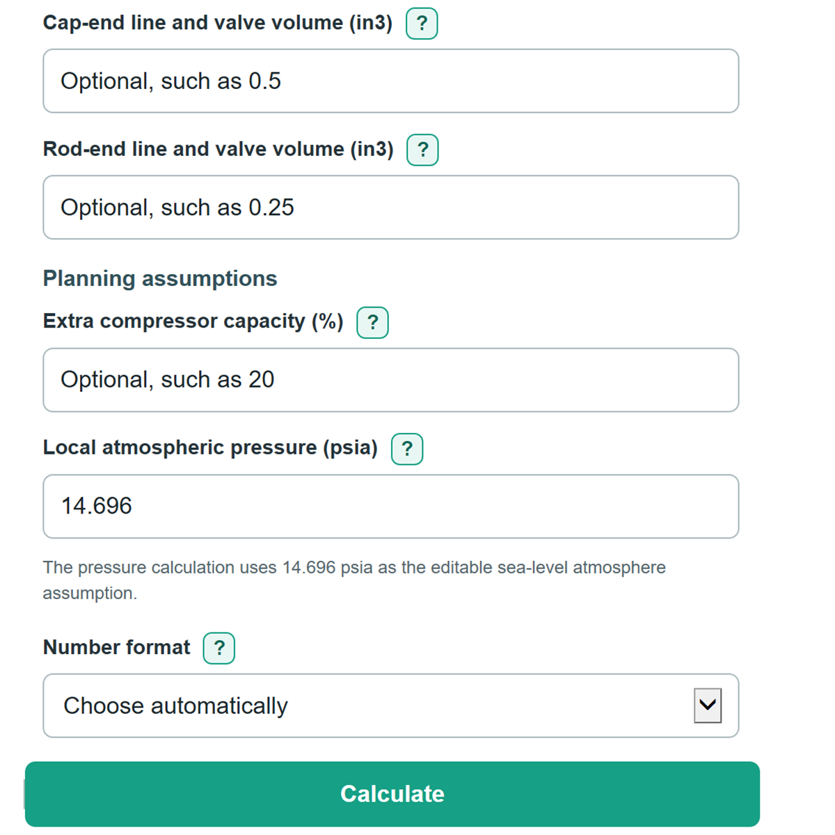
Mistake: Adding guessed values for Cap-end line and valve volume (in3) or Rod-end line and valve volume (in3).
Fix: Leave unknown line volumes blank, or calculate them from actual tube inside diameter, length, valve, and fitting data.
Limitations & Key Assumptions / Boundary Conditions
- The result covers one group of identical cylinders. Add separate groups, tools, vacuum generators, blowoffs, leaks, and other air loads outside this calculation.
- It assumes each entered cylinder completes the stated full stroke at the entered cycle rate and regulated pressure.
- Peak flow is based on the entered number of cylinders moving at the same time. It does not model the exact timing of individual extension and retraction events, receiver storage, pressure drop, pipe friction, valve flow limits, or compressor control response.
- Average air use applies Active time during the planning period to all installed identical cylinders. It is a planning average, not a guarantee of short-term supply capacity.
- Blank line-volume and extra-capacity fields are treated as zero. Enter measured cap-end and rod-end volumes when short strokes or long hose runs make dead volume important.
- The pressure ratio uses the entered local atmospheric pressure, defaulting to 14.696 psia. Change it if your local engineering conditions require a different value.
- Compare SCFM with a compressor rating at the operating pressure you need. Tank size and motor horsepower alone do not state usable air delivery.
Methodology
Calculation method
The calculator finds the cylinder volumes, converts them to equivalent free-air volume with an absolute pressure ratio, then multiplies by complete cycles per minute. For a double-acting cylinder, the retract side uses the smaller annular area. The underlying cylinder air-consumption approach uses swept volume and absolute pressure rather than gauge pressure alone. [1]
Cap-end area = π x bore squared / 4
Retract area = cap-end area - (π x rod diameter squared / 4)
Pressure ratio = (regulated pressure in psig + local atmospheric pressure in psia) / local atmospheric pressure in psia
Extension free air per cycle = (cap-end area x stroke + cap-end line volume) x pressure ratio / 1728
Retraction free air per cycle = (retract area x stroke + rod-end line volume) x pressure ratio / 1728
Free air per complete cycle = extension free air per cycle + retraction free air per cycle
Peak simultaneous cylinder demand = free air per complete cycle x complete cycles per minute x cylinders moving at the same time
Duty-adjusted average air use = free air per complete cycle x complete cycles per minute x identical cylinders installed x active time / 100
Compressor flow to plan for = peak simultaneous cylinder demand x (1 + extra compressor capacity / 100)
Worked example
For a double-acting cylinder with a 2 in bore, 0.625 in rod, 4 in stroke, 80 psig, and 30 complete cycles per minute, the pressure ratio using 14.696 psia is about 6.4437. With four installed cylinders, two moving together, 25% active time, 0.5 in3 cap-end volume, 0.25 in3 rod-end volume, and 20% extra compressor capacity, the calculated compressor planning flow is about 6.62 SCFM. The peak demand is about 5.52 SCFM, while the duty-adjusted average is about 2.76 SCFM.
Rounding
Areas and free-air volumes are calculated before display rounding. The conversion uses 1 ft3 = 1,728 in3. Blank optional line volumes and extra compressor capacity are treated as zero.