
Enter RF stages in signal-flow order to calculate total gain, cascade noise figure, and input- and output-referred IP3.
Advanced options
Table of contents
How to use our Cascaded RF Gain, Noise Figure and IP3 Calculator
- Replace the example RF stages with your chain, keeping the first component nearest the signal input.
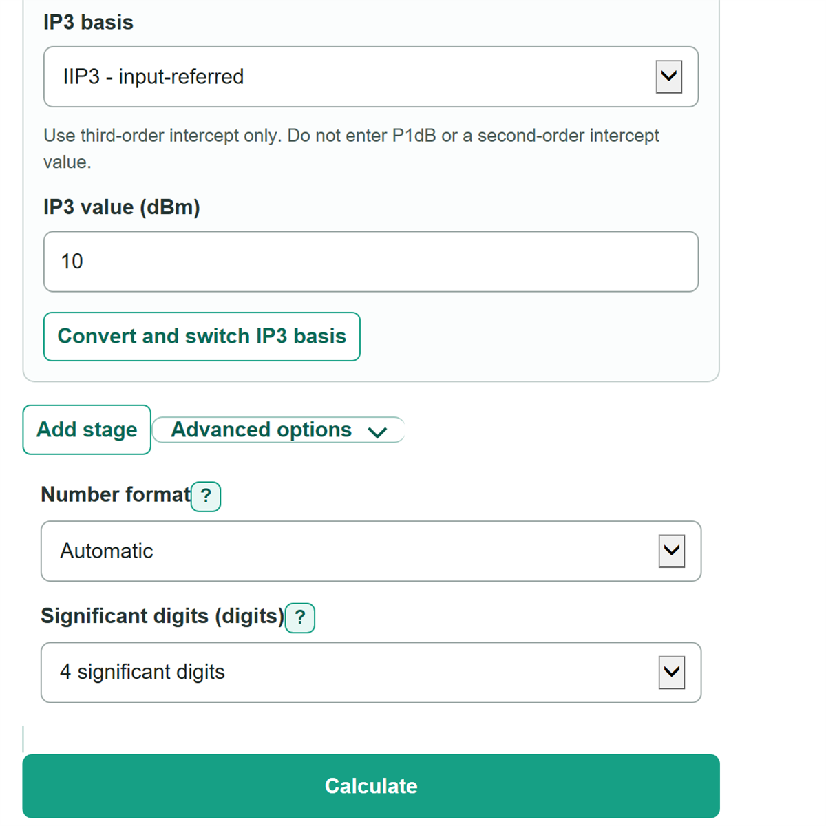
- For each active stage, enter Gain (dB), Noise figure (dB), choose IIP3 or OIP3, and enter the matching IP3 (dBm) value.
- For each passive stage, enter positive Loss (dB); its noise figure is treated as equal to its loss.
- Click Calculate, then check that Total cascade gain matches the signed gains and losses you entered.
- Use Cascade input IP3 for an input reference plane and Cascade output IP3 for an output reference plane; change Significant digits only to match your source precision.
Definitions
Gain (dB): Change in signal power through a stage. Positive dB means gain; negative dB means loss.
Loss (dB): Positive attenuation entered for a passive component such as a filter, cable, or attenuator.
Noise figure (dB): Noise added by a stage compared with an ideal noiseless stage. Lower is better.
Noise factor: The linear version of noise figure used in the Friis cascade equation. A noise figure of 0 dB has a noise factor of 1.
IIP3: Third-order intercept point referred to a device or chain input, expressed here in dBm.
OIP3: Third-order intercept point referred to a device or chain output, expressed here in dBm.
dBm: A power level relative to 1 mW. For example, 0 dBm equals 1 mW.
Friis cascade equation: A noise calculation in which later-stage noise is reduced by the gain before it. [1]
Common mistakes and quick fixes
Mistake: Putting a 3 dB filter loss into RF stages as -3 dB.
Fix: Choose the passive stage type and enter Loss (dB) as positive 3.
Mistake: Copying an output-referred datasheet IP3 while IIP3 is selected.
Fix: In RF stages, choose OIP3 for a value specified at that stage's output.
Mistake: Entering a linear noise factor in a Noise figure (dB) field.
Fix: Convert the source value to dB first, then enter it in RF stages.
Mistake: Mixing values from different frequencies, bias points, or temperatures in RF stages.
Fix: Use specifications measured under the same operating conditions for every stage.
Mistake: Reading Cascade output IP3 as an input-referred number.
Fix: Use Cascade input IP3 at the chain input, and use Cascade output IP3 at the chain output.
Mistake: Showing more Significant digits than the datasheet supports.
Fix: Set Significant digits to match the least precise important source value.
Limitations & Key Assumptions / Boundary Conditions
- Results use ordered, matched-stage cascade equations. Impedance mismatch, reflections, and frequency-dependent matching are not modeled.
- Use gain, noise figure, and IP3 values measured at compatible frequency, bias, temperature, impedance, and two-tone spacing conditions.
- A passive stage is modeled with noise figure equal to its positive loss. This applies to a matched passive device at the reference temperature.
- IP3 is a weakly nonlinear intercept approximation. Results do not predict compression, P1dB, spurs under all signal conditions, SNR, noise floor, or SFDR.
- Negative active gain is allowed for devices such as conversion-loss mixers, but the copied specifications must use compatible reference planes.
- Displayed Significant digits change only rounding. They do not increase the accuracy of datasheet or measured inputs.
Methodology
Stage preparation
Each active stage uses its entered gain and noise figure. Each passive stage uses negative gain equal to its entered positive loss, and its noise figure equals that loss. OIP3 entries are converted to input-referred IP3 before the chain is combined.
gain_dB_i = active_gain_dB, or -passive_loss_dB
gain_linear_i = 10^(gain_dB_i / 10)
noise_factor_i = 10^(noise_figure_dB_i / 10)
stage_IIP3_dBm_i = entered_IP3_dBm for IIP3; entered_IP3_dBm - gain_dB_i for OIP3
Gain and noise figure
Total cascade gain is the sum of the signed stage gains. Cascade noise factor uses the Friis method: each later stage's added noise is divided by the product of the earlier linear power gains. [1]
total_gain_dB = sum(gain_dB_i)
cascade_noise_factor = F1 + sum((Fi - 1) / preceding_gain_product_i)
cascade_noise_figure_dB = 10 * log10(cascade_noise_factor)
IP3 calculation
The calculator converts every stage IP3 to mW, adds its input-referred reciprocal contribution after accounting for preceding gain, then converts the combined power back to dBm.
stage_IIP3_mW_i = 10^(stage_IIP3_dBm_i / 10)
cascade_IIP3_mW = 1 / sum(preceding_gain_product_i / stage_IIP3_mW_i)
cascade_IIP3_dBm = 10 * log10(cascade_IIP3_mW)
cascade_OIP3_dBm = cascade_IIP3_dBm + total_gain_dB
Worked example
For two amplifiers with 10 dB gain each, 3 dB noise figure each, and IIP3 values of 0 dBm and 10 dBm, total gain is 20 dB. The calculated cascade noise figure is about 3.211 dB, cascade input IP3 is about -3.010 dBm, and cascade output IP3 is about 16.990 dBm.