
Enter a known heat load and four connection temperatures to calculate LMTD and the required heat-exchanger UA.
Table of contents
How to use our Heat Exchanger LMTD and Required UA Calculator
- Enter the Heat load and choose the exact Heat load unit shown on your schedule or calculation.
- Choose the shared Temperature unit, then enter the hot and cold stream temperatures at their inlet and outlet connections.
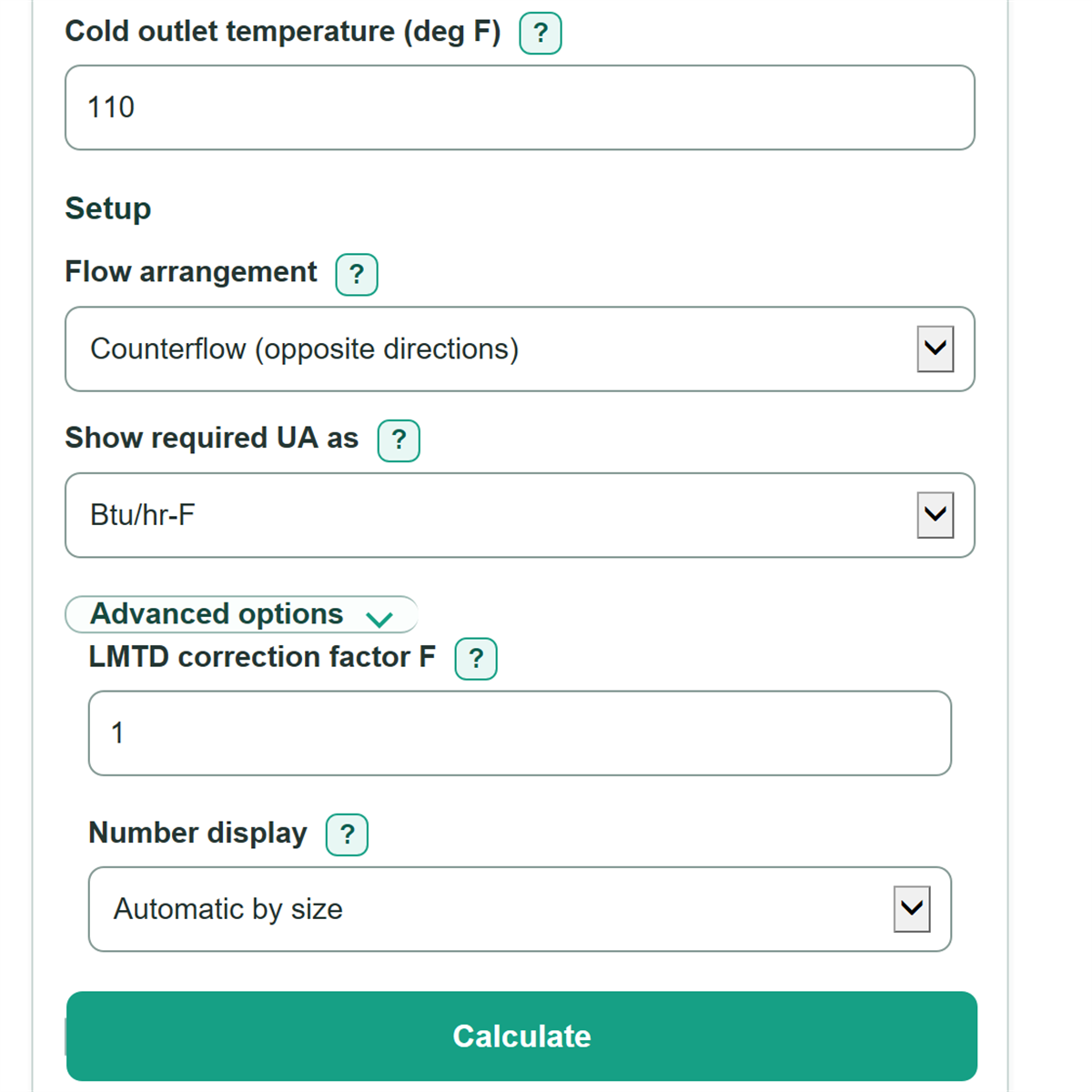
- Choose Flow arrangement. Use counterflow for fluids moving in opposite directions and parallel flow for fluids moving in the same direction.
- Choose how to show the answer with Show required UA as. Open Advanced options only if you have a manufacturer or thermal-design value for LMTD correction factor F.
- Click Calculate. Check that Temperature setup check is valid and both terminal temperature differences are positive before using Required heat-exchanger UA for preliminary comparison.
Definitions
Heat load: The target rate of heat transfer through the exchanger. The calculator accepts Btu/hr, MBH, refrigeration tons, or kW.
MBH: A heat-load unit equal to 1,000 Btu/hr.
Refrigeration ton: A heat-load unit equal to 12,000 Btu/hr.
Terminal temperature difference: The hot-fluid temperature minus the paired cold-fluid temperature at one end of the exchanger. Both differences must be greater than zero.
LMTD: Log mean temperature difference, an effective average temperature driving force calculated from the two terminal temperature differences. [2]
LMTD correction factor F: A dimensionless multiplier applied to LMTD. This calculator uses 1 when the field is blank; a geometry-specific value may be needed for non-ideal arrangements.
UA: Overall heat-transfer conductance, equal to overall heat-transfer coefficient U times heat-transfer area A. It is not area alone.
Common mistakes and quick fixes
Mistake: Entering MBH as if it were Btu/hr in Heat load.
Fix: Choose MBH (1,000 Btu/hr) under Heat load unit ; 120 MBH means 120,000 Btu/hr.
Mistake: Entering terminal temperature differences instead of connection temperatures in Hot inlet temperature, Hot outlet temperature, Cold inlet temperature, and Cold outlet temperature.
Fix: Enter the four actual fluid temperatures from the exchanger connections. The calculator finds the differences.
Mistake: Choosing counterflow when both fluids enter at the same end.
Fix: Set Flow arrangement to Parallel flow (same direction), then confirm the positive values shown for both end temperature differences.
Mistake: Leaving Temperature unit at deg F while copying temperatures reported in deg C.
Fix: Choose deg C before entering all four temperatures. Do not mix deg F and deg C in one calculation.
Mistake: Using a guessed value below 1 for LMTD correction factor F.
Fix: Leave F blank or enter 1 for the ideal calculation. For multipass or crossflow equipment, copy F from manufacturer selection data or geometry-specific thermal documentation.
Mistake: Treating Required heat-exchanger UA as exchanger area.
Fix: UA is overall U multiplied by area. Use the UA target for comparison, then obtain area from a suitable overall U value or manufacturer selection.
Limitations & Key Assumptions / Boundary Conditions
- This is a duty-first preliminary sizing calculation. It needs a known target heat load and does not calculate load from flow rate, fluid properties, or measured energy use.
- The calculation assumes the hot stream cools and the cold stream warms. It blocks temperature relationships that do not fit that hot-to-cold duty setup.
- Counterflow and parallel flow determine terminal-temperature pairing. Multipass and crossflow exchangers can need a geometry-specific correction factor F from manufacturer or thermal-design information.
- A valid temperature setup check means the LMTD math is defined. It does not verify fouling, pressure drop, flow distribution, phase change, heat loss, control behavior, material limits, or actual exchanger capacity.
- Required UA is a conductance target, not a final area or equipment selection. Final selection also depends on the selected overall U value, allowable pressure drop, fluids, fouling allowance, and vendor thermal rating.
- A zero Heat load correctly returns zero required UA when the entered temperatures are otherwise valid.
Methodology
Calculation method
The calculator first converts the entered heat load to a common basis. MBH is multiplied by 1,000, each refrigeration ton is multiplied by 12,000 Btu/hr, and kW is converted to watts. The Btu/hr-to-watt conversion used is 0.29307107. [1]
For counterflow, end 1 pairs hot inlet with cold outlet, and end 2 pairs hot outlet with cold inlet. For parallel flow, inlet temperatures pair together and outlet temperatures pair together.
ΔT1 = hot inlet - paired cold temperature at end 1
ΔT2 = hot outlet - paired cold temperature at end 2
Both terminal temperature differences must be positive. If they are equal, LMTD is that shared value. Otherwise, the calculator uses the logarithmic mean temperature difference equation. [2]
LMTD = (ΔT1 - ΔT2) / ln(ΔT1 / ΔT2)
The correction factor F adjusts the ideal temperature driving force. ASHRAE describes F as less than 1 for exchanger arrangements that do not follow true counterflow; this calculator uses 1 when the field is blank. [3]
Corrected driving force = LMTD x F
Required UA equals the normalized heat load divided by the corrected driving force. The calculator converts temperature differences by 5/9 when needed for W/K; it does not apply an absolute-temperature offset.
Required UA = heat load / corrected driving force
Worked example
With 120 MBH, counterflow temperatures of 180 deg F hot in, 140 deg F hot out, 80 deg F cold in, and 110 deg F cold out, the two terminal differences are 70 deg F and 60 deg F. LMTD is about 64.87 deg F. With F = 1, the required UA is about 1,850 Btu/hr-F.